Most commented posts
- Resistor Decade Box — 15 comments
- Desoldering Station — 12 comments
- 3D Printer UV Curing Device — 6 comments
- ESR-Meter – Update — 4 comments
- Dust extraction – Part 4: Solid State Relay — 4 comments
Jan 02 2011
I had a fluorescent light above my desk. The buzz from the coil in that light was quite annoying. If I was hobbling it was ok, but when I was studying it was not. So I replaced it with some led strip.
Front:

The led strips:

I’ve put a switch on the right corner. From the front this is not visible.

Jan 02 2011
Some time ago I came across 2 loose Incandescent light bulb. I sometimes use these to test dimmers. But I find it annoying that they roll of my desk and are so fragile. Therefore I made a case around them.

For the front I used a layer of red pvc on top of blue pvc. By doing this it reduces the intensity very much. Now I can look directly in to a 100W lamp.
Picture with the 25W lamp burning:

I drilled a 74mm cooling hole on each side of the case and glued some mesh to it.


Jan 03 2011
Some time ago Reddevil gave me 6 led panels from a led sign. (Story [Dutch] can be read here: http://www.schematheek.net/index.php?p=forum/topic&t=337)
I made a frame from din rail to mount the panels on:

I also thought of how I’m going to make the power supply.
For every 2 panels there will be a transformer, rectifier, capacitor and voltage regulator. The voltage regulator will be a diy one that consists of a 2N3055 tor and a opamp)

Circuit power supply:


The LED sign is going to be controlled by a pc via usb. The usb gets “translated” to the signals for the led panels by this pcb:
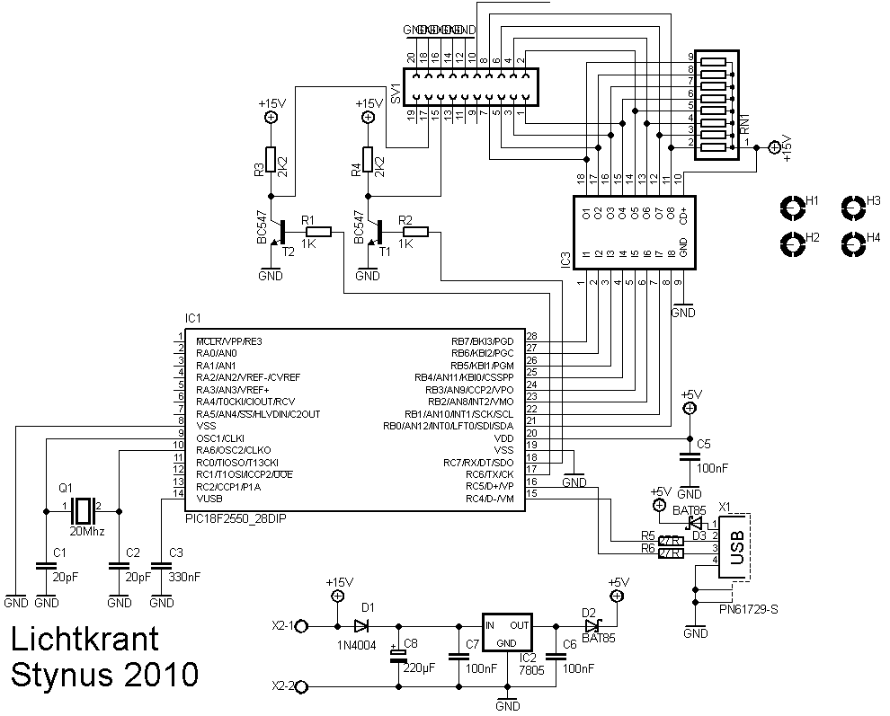


All the pcb’s and transformers mounted on the frame:


2 test video’s:
The spreadsheet I used to draw the drawings: https://spreads…NWmdzcUE&hl=en
The next step will be getting the usb interface working. Then I’m going to make a pc program to drive the led sign. Maybe I even include pwm to dim pixels for video.
Jan 03 2011
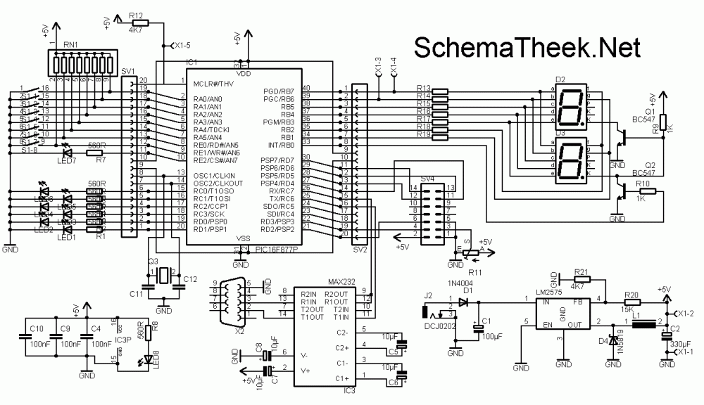
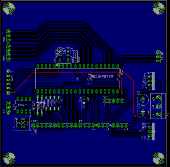
After building my first development board I decided to build a second one. This one is going to work with a PIC16F877
The functions will be:
-7x Led
-8x dipswitch
-2x 7 segment display
-1x Lcd
-1x RS232 connection
-1x program plug (wisp or pickit layout, depending on installed connector)
I have placed 2 rows of female header cups next to the pic, to make it easy to connect this board to a breadboard.
The circuit:
The pcb layout:

Some pictures from the first prototype:


Video of the first test:
The serial interface and the lcd are also working already:

For the final version I had this pcb professionally etched:


Files
Demo code:
Hex file: Download.
Circuit diagram:
Available Products:
Jan 03 2011
I’m building another power supply. The specs of the power supply will be 0-24V at 6A, but they can be easily adjusted to your own needs.
Pictures of the parts that are ready:
The back side and heat sink:

The volt and ampere meter:


The help power supply:


Jan 04 2011
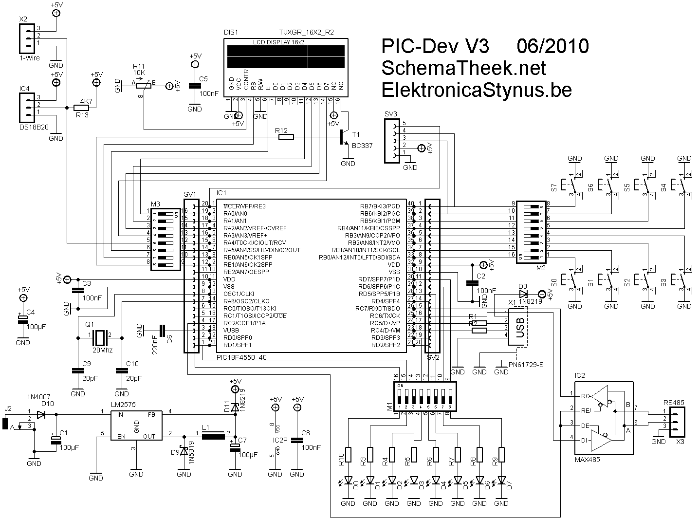
I wanted to use a usb connection on my LED sign. Now is the problem that this led sign is a bit big to put next to the pc, and a little difficult to debug the usb that way. So I decided to build another development board. This time based on a PIC18F4550
Functions:
-USB
-LCD
-8 buttons
-8 led’s
-1 wire bus (and 1 temperature sensor that’s connected to that bus on the pcb)
-RS485 bus
-I have placed 2 rows of female header cups next to the pic, to make it easy to connect this board to a breadboard.
-Most of the pins of the pic are detachable from the other components by dipswitches
-Power via USB or power supply
-ICSP header (galva)wisp pinout
Circuit:
PCB:
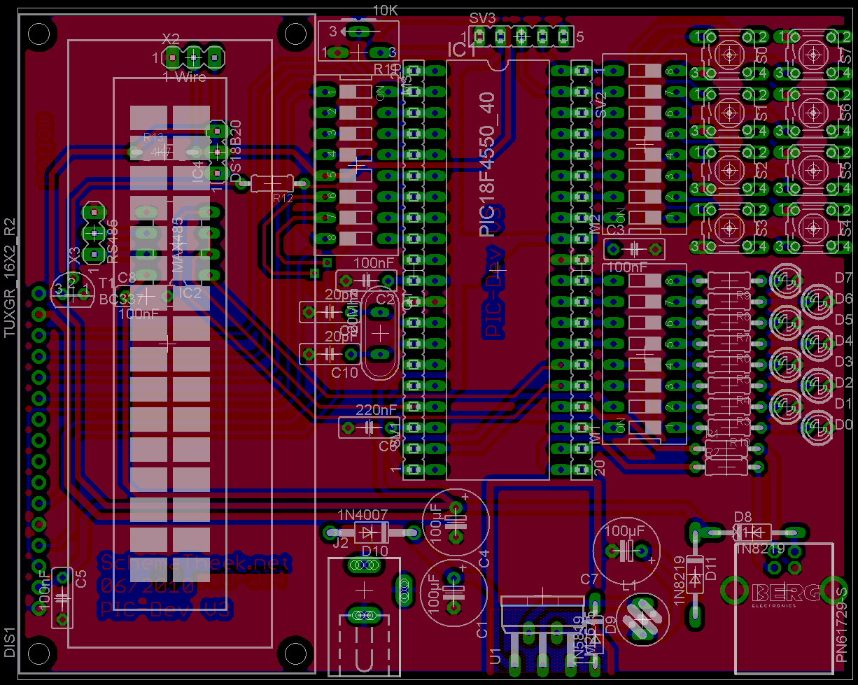
Prototype:


Jan 05 2011
The switch clock from the lights on the driveway had died. Therefore I want to build a new one, the new one will have a input for an ldr. So the time does not need to be altered for different sunsets.
To keep the time I used a DS3232 real time clock.
Design:

Pcb:
Control interface:

The assembled pcb:


The front in progress:

Inside:


Finished:


Video:
Jan 06 2011
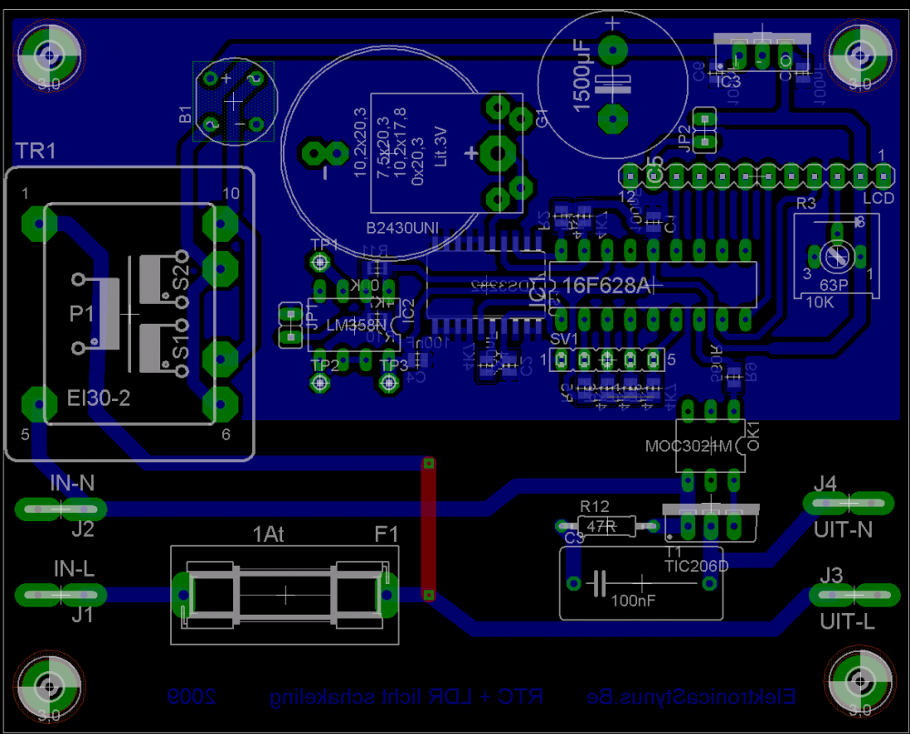
I made a pcb to control a electric shutter. When it gets to dark outside it closes and when it’s back light enough it opens again. There are also 2 inputs for manual overwrite with a switch.
The light sensor is a LDR, the motor to operate the shutter is a 230V tube motor specially designed for this purpose (it has end stops build in).
The circuit:
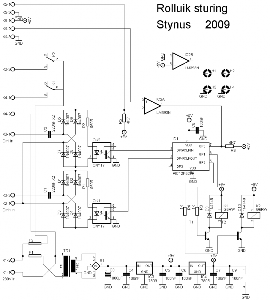
The pcb lay-out:


Jan 06 2011
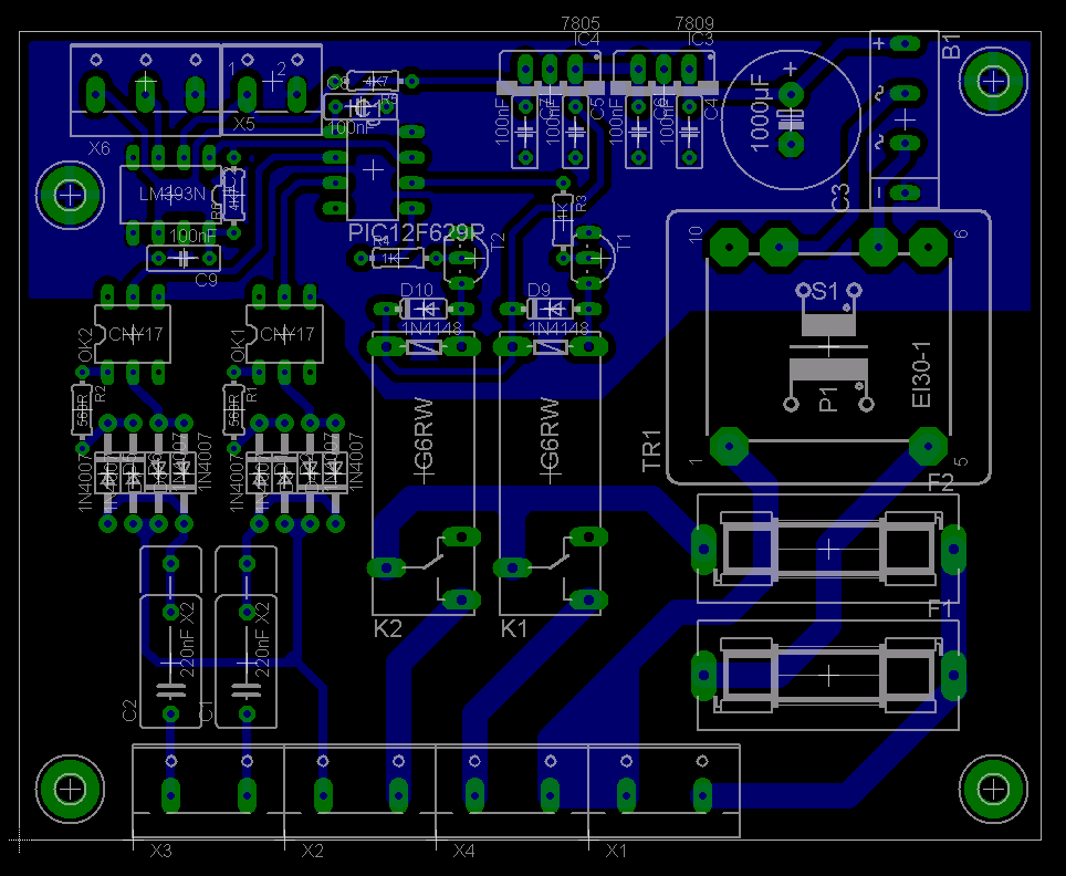
This update was already planned in October 2009, but I didn’t put it on my site until now.
I made a pcb for the help power supply. First I added a few extra coils on the main transformers, but the voltage was too low, so I removed them and bought some print transformers
The pcb:

Mounted:

The analog print is also finished


When I wanted to test the analog print I looked at my circuit drawings before. Then I noticed that the analog print works on 2*5V while the power supply outputs 2*12V. So I designed the digital pcb and put a 7805 and a 7905 voltage regulator on that.


I made a small pcb to connect the lcd with the digital pcb. The connector from the lcd had a two small pitch to solder strong wire to it. So I glued the pcb on the lcd, connected it with small wires to the lcd and soldered “big strong” wires on it to go to the digital pcb.


Jan 06 2011
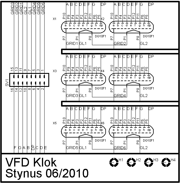
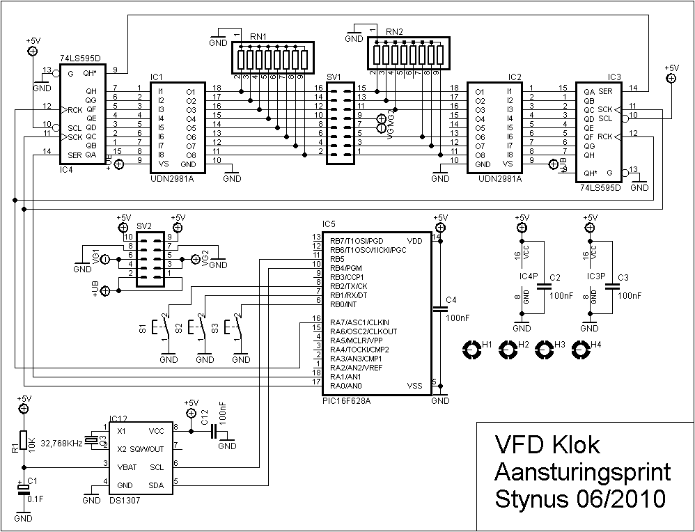
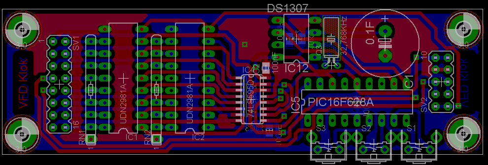
Some time ago I got a few vfd tubes from Reddevil (Story [Dutch] Link). Now I want to make a clock with them (Like I don’t have enough clocks yet ![]() )
)

The design is build quite similar to my latest nixie clock ( It is divided in 3 layers).
I could not find a datasheet for the dg10f1 tubes, so I’m basing my circuit on the circuit from this site: Link
Top layer:
(Tube layer)


Middle layer:
(Drive circuit layer)
Middle layer:
(Power supply)


