Most commented posts
- Resistor Decade Box — 15 comments
- Desoldering Station — 12 comments
- 3D Printer UV Curing Device — 6 comments
- ESR-Meter – Update — 4 comments
- Dust extraction – Part 4: Solid State Relay — 4 comments
Mar 03 2011
Now I mounted LED lights on my other desk too. This way I save a lot of workspace where the desk lights stood before.


I put a second LED strip at the soldering part of the desk for some extra light.

Mar 06 2011
Because I fitted my work desk with led lighting, my usb lcd and winamp remote control had to be removed. So it is time to make a new version of these 2 projects. I’m also going to ad a 2 channel led dimmer and a fan control.
I already posted a preview from 1 of the buttons of the winamp remote control:
The pcb of the usb-lcd is going to be replaced by a new version. This new version has connections for the buttons and 2 bicolor leds and the led in the big button.
The design from te new usb-lcd version (USB2LCD+) can be found here: Link

I did not use the design from that site because I wanted to mount the pcb directly to the back of the lcd. On the pcb there is also space for a voltage regulator to power the backlight from 12V.
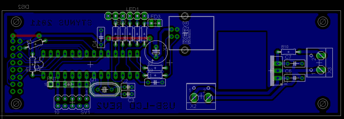
The contrast of the lcd is controlled by the pic in this circuit. This didn’t seem to work after testing. Therefore I added a potmeter and connected that to the contrast pin.

The dimmer is build with a pic microcontroller. The potmeters are switched as a voltage divider and connected to the analogue inputs. The fan and leds are controlled by pwm from the output of the pic.
The reason I don’t use a 555 for this is that the duty cycle can’t go lower than 10% and can’t get higher than 90%. And this can all be placed in 1 pic.


The enclosure is build from 2 pieces of plate steel from an old cd-rom player. I soldered these together and reinforced them with a piece of L bracket aluminum. After the drilling and sawing I applied putty to the front and spray painted it.
Putty:

Base coat:

First coat black finish:

Painting complete:

Assembled with buttons and lcd:

Rear with lcd print:


The pcb for the dimmer is not made yet.
Mar 19 2011
The led strips where powered by an old pc power supply that was standing in a corner of my desk. I had to place resistors on the 5V line to get the power supply stable because the 12V output was the only output in use. This was a waste of energy, so I bought a 150W 12V power supply to power my led strips and a few other appliances.

The power supply is mounted behind my equipment, therefore I got some more workspace.

Before:

After:

Mar 19 2011
Today I finished the dimmer pcb. Now it I need to write the software for the pic.


Mar 26 2011
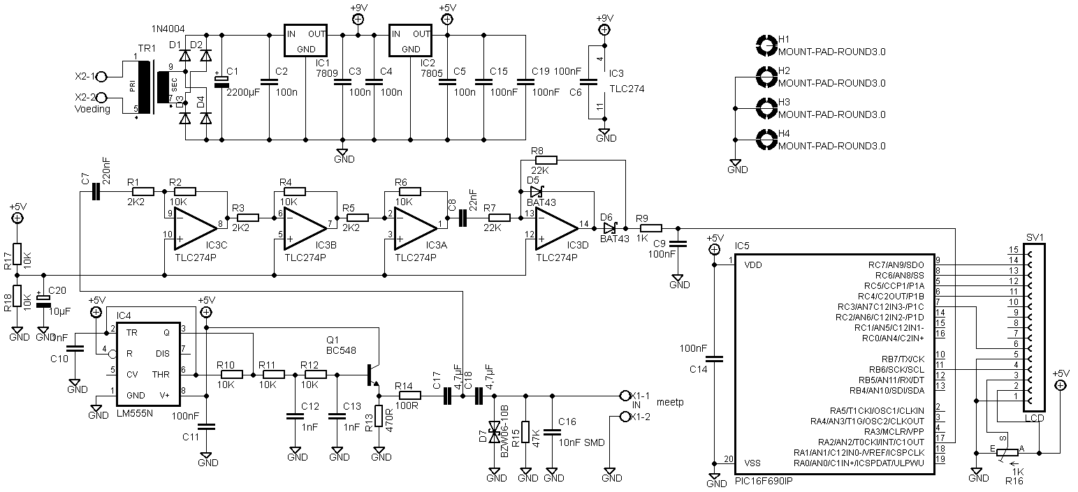
There was another adaptation on the pcb that was not in the circuit diagram above.

The LCD has to be connected differently. I don’t know why anymore, but here is the new circuit diagram:
I received Eagle files from Predrag Mihajlovic for this esr meter. They can be downloaded here: Link.
Hello,
I did 2 versions. First is one based on your schematics, except that I’ve changed those smd capacitors for standard through hole ones. Second one is somewhat modified. I’ve excluded transformer and put in standard dc jack. Also, pic and display header are located so far away from other stuff so that there is enough place for display to be on the pcb. Also, you’ll see that, on both versions I’ve also put pads for 27 and 22mm capacitors (4.7uF). Check it out and feel free to make any modifications you think are necessary. You can put it on your website if you like, maybe someone will find it useful 🙂
Peca.
Mar 26 2011
At request I changed the code to a 12h version. However the time still needs to be entered in 24h mode because there is no AM/PM indicator, otherwise it can happen that the date jumps forward at noon instead of midnight.
12h code: Download.
Mar 27 2011
Today I finished the code of the dimmer and connected it all to the led lights and the solder fume extractor.
A video of the dimmer working:
Some pictures:


Apr 03 2011
I decided to build a new design because I’m afraid that the solar cells are not going to be powerful enough. I’m going to use 50F 2,7V capacitors instead of batteries in the new design. After the capacitors I placed a dc-dc converter.
The pcb with the capacitors and the dc-dc converter is now ready, the converter is based on a MAX1676 with an external diode to work at an even lower input voltage.
I mounted some zenerdiode’s on the bottom side of the pcb to protect the capacitors from overcharging.
Circuit:
PCB:

Pictures:


The main print will also get a new version. That will be based on a PIC16LF1827, this pic has nanoWatt XLP onboard so it uses very little power. The sensor’s also will be connected differently so they consume less power. More info about this will follow later.
Apr 16 2011
I wanted to build an extra clock with some extra nixies I had laying around. Therefore I had some pcb’s made, that way it looks a bit more professional. The old clock above will probably be taken apart en mounted on a new pcb.
The pcb without components:

Milling the tabs of the pcb:
Clock ready (With the old clock in the background):

Files:
Downloads: – PCB files: Download
– Code: View
– Code: Download
-12h code: Download
-Partlist: Download
Datasheets – 16F628A
– IN-14
– DS18B20
– DS1037
– 74141
– 74HC595
Apr 17 2011
Today there was a Radio flea market in Lummen.
What I bought (for 51€ including entrance fee):
1x Power supply 48V 600W
1x Crimping tool for amp connectors
6x Capacitor 4700µF 50V
1x Solid state relais
1x Camera module
10x knobs

