Most commented posts
- Resistor Decade Box — 15 comments
- Desoldering Station — 12 comments
- 3D Printer UV Curing Device — 6 comments
- ESR-Meter – Update — 4 comments
- Dust extraction – Part 4: Solid State Relay — 4 comments
May 23 2010
The code is finished. I left the connection with the pc out because the crystal had too much drift through the temperature rise and that caused the connection to drop out. (visual basic is very critical what the timing matters).
The code can be found here: Link
A few pictures of the finished oven:


A second part of the assignment in school was to design a pcb based on the pcb of the reflow oven.
The demands where:
My colleague designed the pcb and I soldered it.

Files
Code as html: Download
Code Picbasic + hex: Download
May 28 2010
I came across an ad form Stefan Haesen, he had a bunch of transformers and motors for sale at a low prize. I reacted and a few days later the trunk of my car was full. Thanks Stefan!
Between the transformers there as a 1000VA safety transformer and a 1500VA variac. I decided to build a variable safety transformer with these. For the case I used an old pc case in which I made a chassis. I also have put some wheels underneath it. The measuring print will be the same as in V2.
Because this transformer is big I had to build something to limit the inrush current.
Pictures:
PC case with reinforced bottom and wheels:

Variac:

Front panel almost finished

Inrush current limiter


The power supply:

I build all the pcb’s in the case of a pc power supply. This way it is easy to mount in the big case.


I’m still going to finish my safety transformer V2 because that version has a current limit and this version doesn’t. I have taken V1 apart for the parts.
May 30 2010
I started this project a while ago but did not post it back then because of the lack of time. The point of this project was a simple variable load to test power supply’s. As an extra I put in a voltage, current and temperature measurement circuit.
The power is converted in to heat via 8 2N3055 transistors. Each transistor has his own driver and current feedback. This way I can read then individually in the pic and therefore can check if they are all still in a working state.


There are 2 fans mounted next to the heat sink. The fans suck air to the slots of the heat sink. The temperature is measured with a LM35 which is connected to the pic, so if it gets to hot the pic can shut it all down.
Circuit pic print:


The power supply I used came from an old hub. (From witch I also recycled this enclosure)
The displays are the same as from my safety transformers V2 and V3. I started this project earlier and copied the design to those two projects

Front panel ready:


The voltage and current measurement works at the moment. The current measurement is a bit of a problem. The MAX186 seems not to work (or I’m doing something wrong :p). I didn’t have time yet to fix it. The code will be posted as the project is complete.
Jun 12 2010
Some time ago I came across an ad on eBay for a AMA-16 Milling Machine. This is the same as the more know bf-16 from buitelaar, but it was a lot cheaper because the exchange rate of the pound was bad.
First we needed to construct another workbench. My dad made it from L-profile steel and plywood.
The milling machine is going to be mounted on a steel plate with 2 L profiles directly underneath them.
Sometime after the workbench was finished, DHL delivered a package :).


After milling a few test pieces with thesupplied drill head, I noticed that this was not ideal for milling. So I went to eBay again and bougt a set of ER-25 collets.
Left drill head, right collet:

Mounted and with a mill inside.

To store the mills and collets I hung some drawers on the wall.


After some more drilling the motor overheated. This didn’t surprise me, it is locked up in a tight box with little air gaps. I went looking in my supply closet for a solution and found 2 80mm 110V fans. If I connect these in series then they can work on 230V.
Pictures:
The case that goes around the motor like it is delivered:

After mounting the fans:

The cable comes out at the side and runs into the control box.

I also noticed some place to put a rpm counter. So that’s added to de todo list now ![]() .
.

Another plan is to make something to hold the spindle while I insert a mill. I seen this in a youtube video and it seemed handy to me. http://www.youtube.com/watch?v=4oL-XcKPiKg the part comes around 1min.
Jun 14 2010
Last year I have bought 2 light boards at the radio flea market in Eksel. First I didn’t have a direct use for them, but then I saw a led spectrum analyzer for audio on YouTube, and I decided that this is what I’m going to make with my led boards.
After some searching I found that there are 2 ways of doing this:
-A FFT (fast Fourier transformation) in a microcontroller and output the result on the matrix.
-Build a filter for each frequency and connect them to a AD converter and scan those values over the display.
I chose to use the second way, because I didn’t feel like doing math for my hobby.
The analog filters are based on active bandpass filters with 4 poles.
I found a script to calculate these: Link.
I have designed a pcb with 8 filters on it. I need 3 of those pcb’s per side, so I get 24 channels.
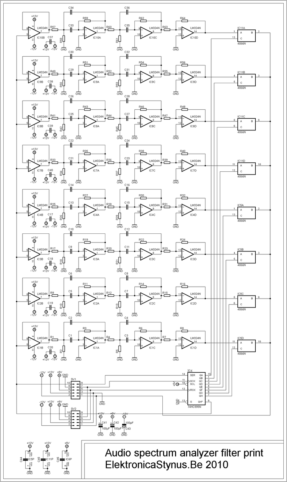 |
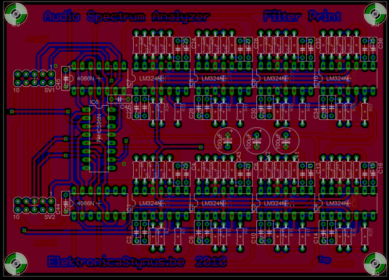 |
The AD converter is build with 8 opamps. The scanning of the displays happens with an PIC16F628A. This pic will drive 2 sets of shift registers. The first group is connected to the columns of the displays. The other will switch the analog voltages to the AD converter. This happens with 4066 ic’s.
 |
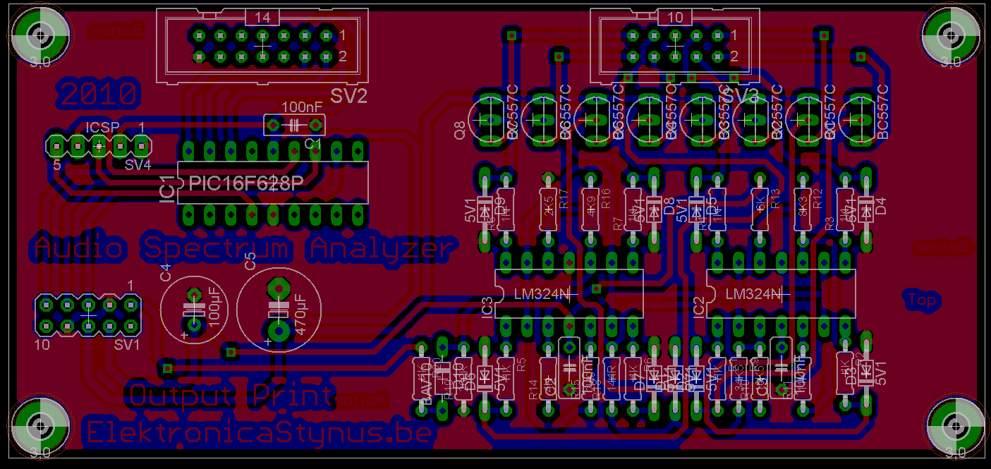 |
I have designed a small amplifier to go at the input:
 |
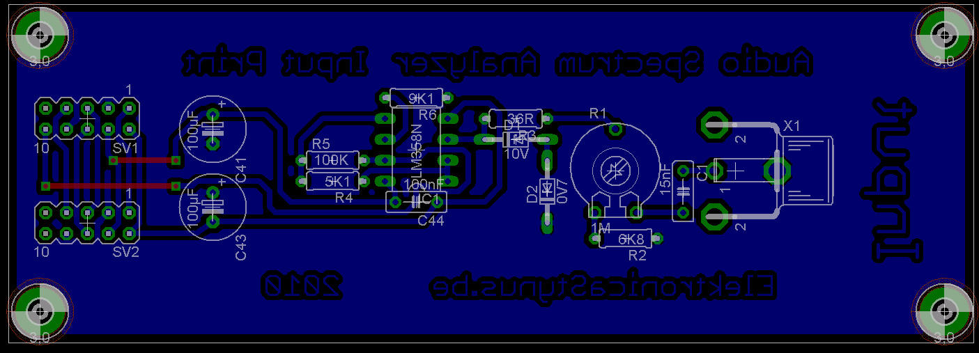 |
The complete circuit will be powered by an 2*12V 24VA transformer. This is also mounted on a separate pcb.
 |
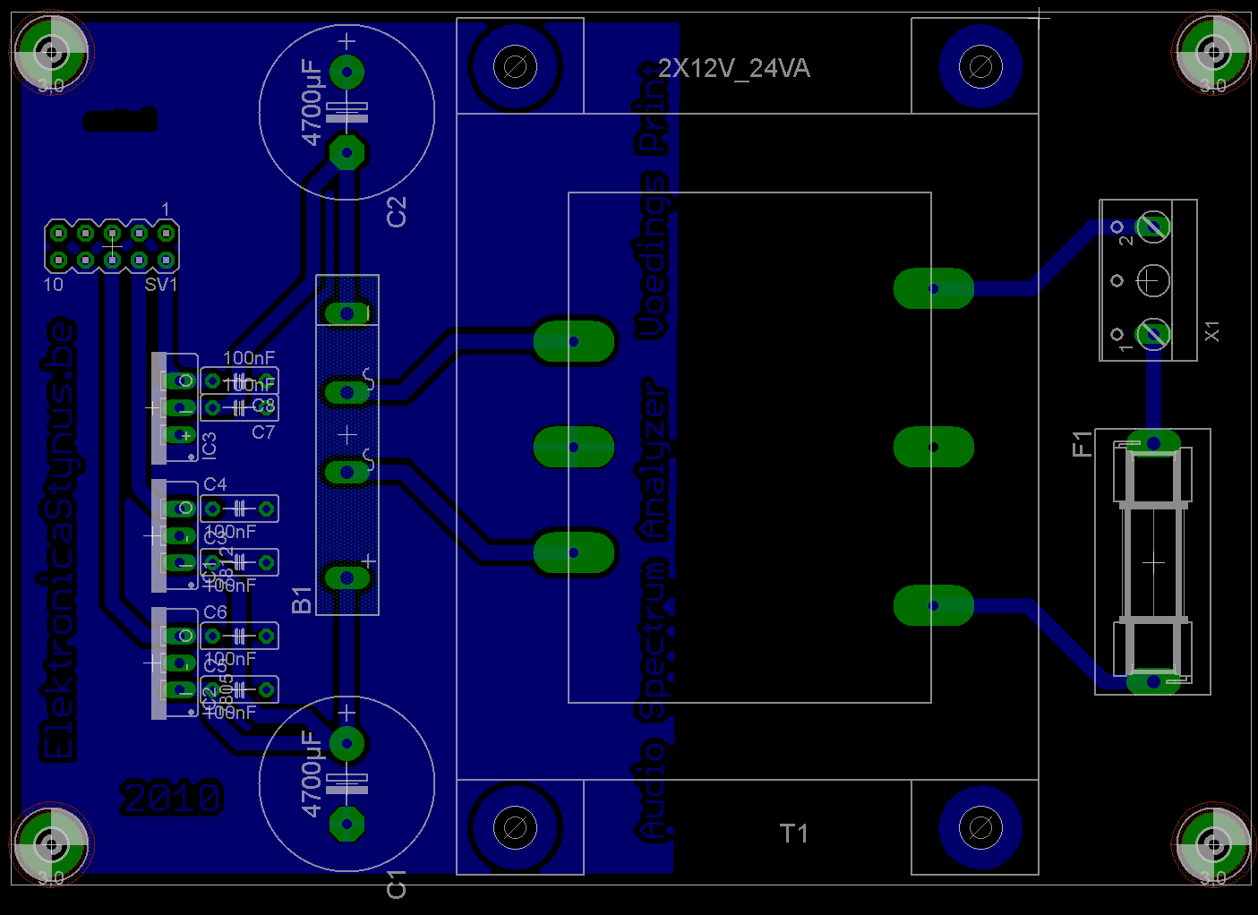 |
The power supply pcb and the input amplifier are finished already.


Jul 27 2010
Some time ago I came across this site: http://www.bwired.nl/ On this site are some graphs of the power consumption etc. of his home. I thought it would be nice to have something similar on my site. Only I’m going to use weather data from a small weather station.
This weather station has the following functions:
-Temperature measurement
-Moist level measurement
-Light intensity measurement
The weather station is going to work with some solar panels (and battery’s to power it at night). Therefore the battery voltage gets read as well. The measurements are transmitted via a 433Mhz transmitter to a pic inside the house. The pic inside is going to be connected to a hacked sweex router to transmit the value’s to my site.
The outside unit:
Circuit & pcb:


Pictures:

The solar panels:

The left panel is from eBay (solar668-solar panel), and the right one from Deal Extreme. The one from eBay was a little bit more expensive but it produces more power with the same area.
The inside unit:
This is not designed yet, but I can already tell that it’s going to work with a hacked sweex router.
Jul 30 2010
I made a case from aluminium around the original case:

After some filler, sanding, filler, sanding, painting, sanding, painting:

The back side (other color):

I had to much voltage drop over the usb-cable (The display uses 500mA). Therefore I made an extra cable that provides 12V from a molex plug inside the pc. In the display case I’ve put a switchmode 5V regulator.
Dec 18 2010
Today I switched to WordPress for my new blog. All the new entry’s will be in English. The old imported entry’s stay in Dutch.
Dec 31 2010
I got my Christmas presents today :).
What I got:
IC extractor
SMD test tweezers
figure sawing aid


