Most commented posts
- Resistor Decade Box — 15 comments
- Desoldering Station — 12 comments
- 3D Printer UV Curing Device — 6 comments
- ESR-Meter – Update — 4 comments
- Dust extraction – Part 4: Solid State Relay — 4 comments
Aug 17 2009
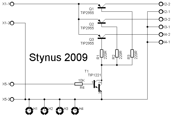
The relays I used as “emergency stop” relays had some trouble with burned and sticky contacts. I replaced it with a bigger 40A relays but that also got the same problems (probably because of the inrush currents). Then I decided to make a solid-state relays with 4 TIP2955 transistors.
The circuit:
To drive this solid state relays and provide 12V for the fan in the back of the case I made a 12V power supply. On the cnc there will be led lighting, and that is also powered by this power supply.
Circuit:


The traces on the underside of the ssr are reinforced with wire so it can handle more current.

I also painted the top of the case.


Aug 21 2009
After a long time I restarted building on this power supply. I found a circuit where I’m going to base it on.

I’m not going to use this circuit exactly, but the main part I do.
In this design they used TIP142 transistors. In my version I used MJ2955 transistors. I was doubting if I would change the design or change the transistors on the heat sink. After a lot of thinking I opted for the second option. The new transistors are mounted directly on the heat sink, where the old ones used an bracket. This should provide a better cooling.

I didn’t trust the big capacitors I first planned to use any more. 1 of the 2 is so dehydrated that if you shake it you hear the inners rumbling louse. Instead of buying new big capacitors I opted to buy a few smaller ones. This is cheaper and gives a lower ESR. To mount them I made a pcb. Per side I use 3 capacitors of 3300µF 100V. That gives a capacity of 9900µF per side, this should be more than enough.

The next update will be the analog print. This design is 90% ready so it should not take too long (if no other project gets in between.)
Sep 23 2009
I made this project for testing amplifiers and cd-players. The output of those comes on the input of this box. Therefore I don’t have to risk my expensive speakers to test a expensive amplifier.
The RCA inputs are amplified by a build in 2x10W amplifier. I can choose between the output off the amplifier and the speaker inputs with a switch. The output of the switch is connected to a dummy load. With another switch the speaker can be switch on and off. To protect the test speakers I made a dc protection circuit
Pictures:


The dummyload:

12V power supply:

Dc protection:

2x10W amplifier:

This project was published in the SchemaTheek magazine of may 2009 (Dutch).
Jan 19 2010
I got 2 register displays. Now I want to connect 1 of them to a pc and control them with lcdsmartie.

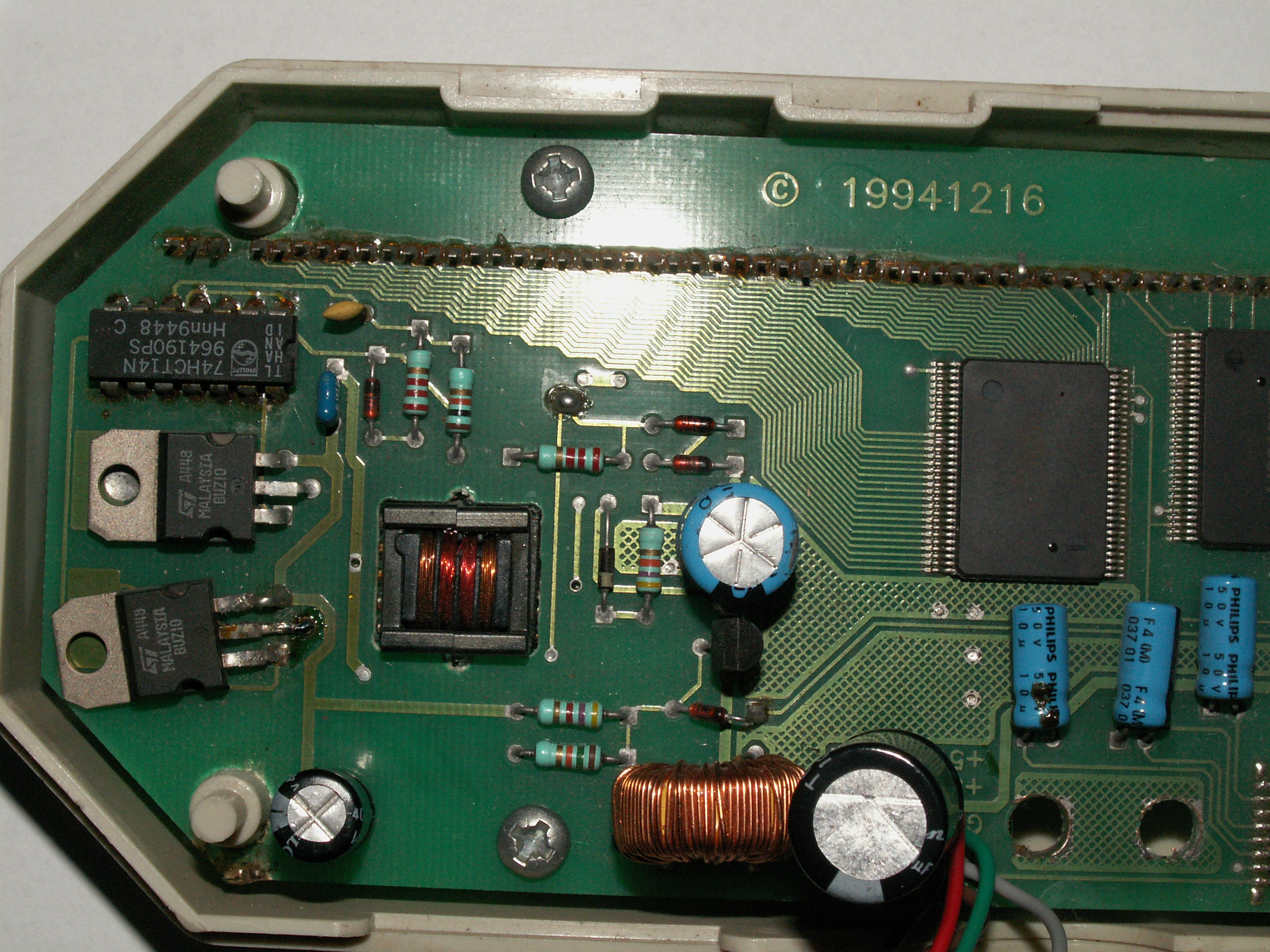
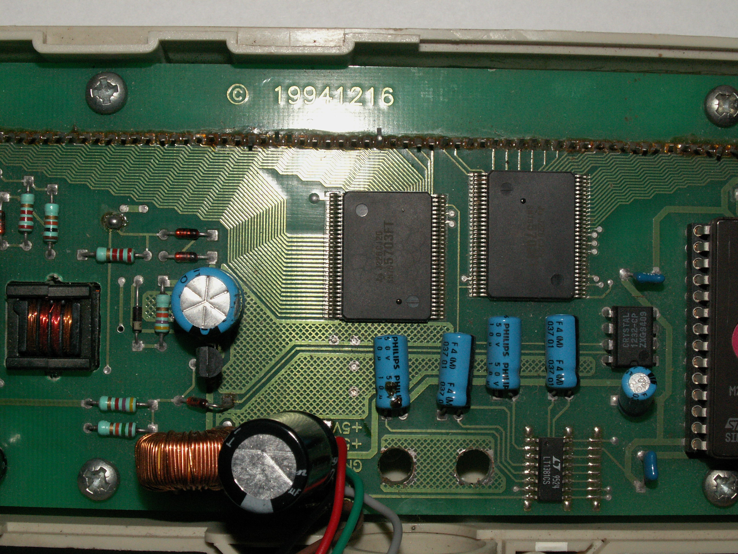
Now is the problem that these displays are not supported by lcd smartie. The display is kind of “stupid”. It can only receive text on a serial interface at 9600 Baud. With only text I mean that it does not know commands to determine the position of the cursor. If you want to go to the first character then you need to send characters until you are there.
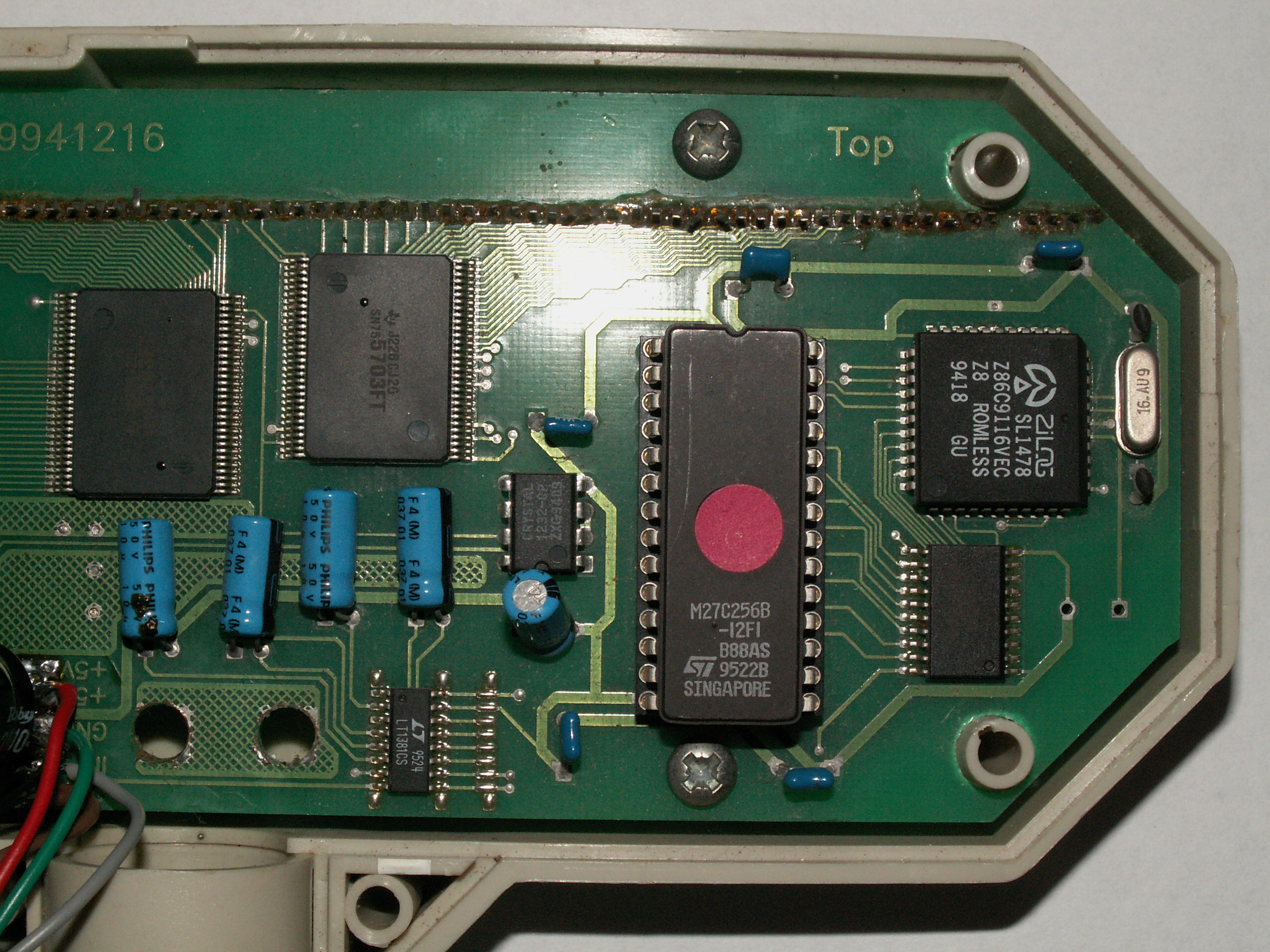
I’m not very good at programming for pc’s so I made a circuit with a pic to translate the commands that are normally intended for a Matrix Orbital lcd to continuous sending of text. The circuit is based on a 16F627A, and is connected to the pc via a FT232. The display is connected through a MAX232. I could do it without the MAX232 if I would desolder the MAX232 on the display itself and connect my signal there but I opted to change nothing on the vfd itself.
The circuit of my controller:
Video of the vfd working:
Sorry for the bad picture quality, it is filmed with my cell phone because the battery’s of my camera where empty.
Jan 21 2010
I wanted to automatically boot a pc at a set time and later to shut it down. The pc is a rather old one so I can’t do it in the bios. Therefore I build this circuit, with 1 relays I switch the power to the PSU and with the other relays I switch the power button.
Circuit:

Pictures:
The pcb:


Front panel:


A video:
Jan 21 2010
Our central heating system had died (the boiler ripped open). Therefore we needed to buy a new one. But the problem was that the new models could only drive 1 pump (unless you buy a very expensive model).
We have 2 zones that are heated separately, so 2 pumps are used. I designed a circuit that receives the 2 signals from the thermostats and combines them to 1 signal to ignite the burner. From the burner there is a signal that tells a pump to work. I connect that signal to my pcb to drive 1 of the 2 pumps. This heater also has a function to let the pump work for a while after the thermostat switches out. So the circuit remembers witch thermostat was on last and leaves the pump on as long as the burner wants.
To build for the future I’ve made the print for 3 zones and placed a header to connect a 433Mhz receiver for a wireless thermostat. The code for this is not ready but the hardware is.
The circuit: |
The pcb layout: |
Pictures:


Connections:

Mar 07 2010
After the electronics from my first nixie clock where ready, I wanted to build a second one. It took some time, but a few weeks ago I bought some IN-14 nixies.
The circuit is roughly the same, only I tried to make it as compact as possible. The complete clock consists of 3 stacked pcb’s. On the bottom pcb is the high voltage supply, the 5V supply, the pic, the rtc and the temperature sensor. On the middle pcb are the 74141 nixie drivers and 74HC595 shift registers. On the top print are the nixies and neon’s.
 |
 |
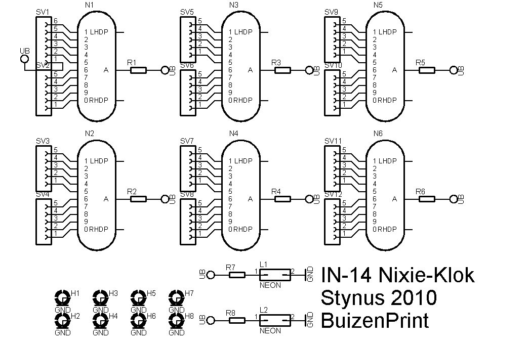 |
This time I used leds to indicate which data is on the nixies (time, date or temperature). This way I can save a lot of pcb space.


I’m basing the enclosure on the Ice Tube Clock from Adafruit:

Display test:
Clock ready:
Mar 18 2010
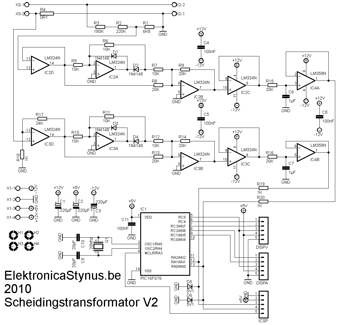
I had a external light bulb in series with my previous safety transformer to limit the output/short circuit current. This gave the problem that sometimes a bulb would fall on the ground with changing it. So I decided to make a new version with the light bulbs inside. The previous version had a 140VA transformer and sometimes that was not enough. So I build a new one with a 300VA transformer.
Measuring PCB:
This time I wanted to put a voltage and current meter in it. I could just buy them, but where is the fun in that? So I made them myself. The voltage is lowered by a voltage divider, then rectified with a opamp precision rectifier. Then it is levelled by a RC filter which sends it in a AD converter. The current is measured with a 0,1 Ohm series resistor. Because off the current there is a voltage drop across the resistor that is proportional to the current. That voltage is amplified an rectified and let to the ad converter in the pic.
 |
 |

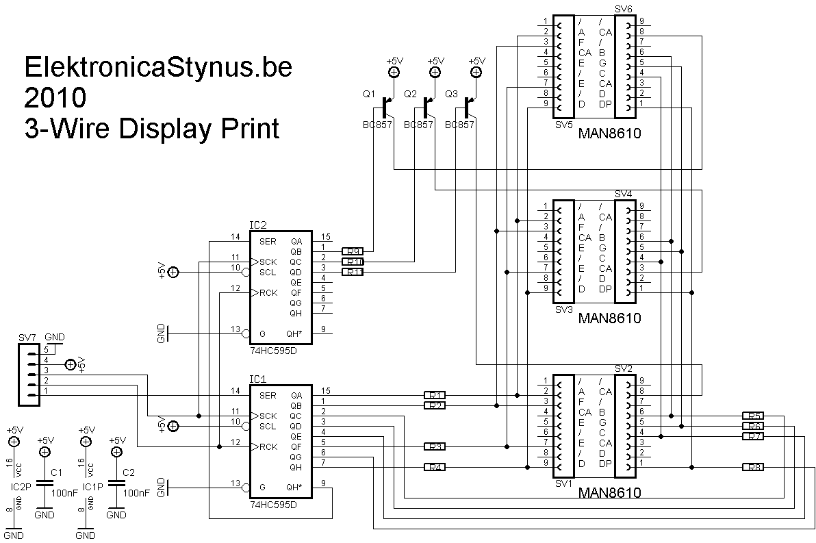
Display
The pic has to drive 6 7-segment displays. To save IO pins to do this I have decided to make a circuit with 2x 74HC595 ic’s. Now it takes only 3 pins per display, so 6 pins in total. 1 of the 2 74HC595 ic’s selects witch 7 segment display is on, the other one drives the digits.
 |
 |


Light bulb indicators
To indicate witch lights are burning I made 3 holes in the front and let some optic fiber from there to the light bulbs.
Power supply
To power these 3 pcb’s I made a separate power supply pcb. It delivers +12V, -12V and +5V.
I used a transformer I had lying around, this transformer outputted 2*24V. This has the disadvantage that the 5V regulator gets very hot if I use a linear one. So I decided to use a switching one.
 |
 |

Main circuit
As you can read above, the current is limited by setting a light bulbs in series with the load. I have put 3 light bulbs in it, via 3 switches the bulbs can be selected. A forth switch can bypass the bulbs. To limit the output current then and switch the output on/off I used a 2A circuit breaker.
If you put 2 transformers “back to back” then you lose some voltage at the output. Therefore I’ve put a 60VA transformer that can put 15V on or of the output.
For the output I used 2 safety plugs and a wall socket.

Picture:

The front panel:

If I receive my PIC16F676 then I can start programming
Apr 16 2010
In school we got the task of making a project for the “measurement and controls” course. It should take a min of 30h time. I decided to finish this project and write a report of it for that course.
The front panel is finished now:

And the backside to. It has a RS232 and programmer interface. And of course the net-plug.

I continued programming while I had vacation, but I quickly got some problems.
First of all the original keyboard was broken (the flatcable broke at the right column). I didn’t have a spare one, so I build 1 myself. I used 14 buttons from Velleman. (Link) The text is put on whit rubbing-letters.
 |
 |
 |
This worked for a while. But then the connectors to it failed trough the thermal cycles. I have replaced the connectors trough flatcable now.
My multimeter has a temperature function with a thermocouple, after I put it in the oven it turned out the thermocouple I had was not fast enough. Then I replaced it with the one from my multimeter.
Now I can continue to program the PID loop in the pic. This doesn’t seem to be as easy as first thought.
Apr 19 2010
I replaced the old thermocouple with the one from my multimeter. I decided to let it hang louse so I can place it against the pcb during reflowing..

I have the PID loop working. After I programmed a reflow cycle it became obvious that the electronics compartment got to hot. So I replaced the fan by 2 50mm fans.

The problem is that these draw much more current then the old fan. Therefore I had to add a second power supply. The fans can still be switched by the main print. I chose a switching power supply so that I didn’t generate to much extra heat in the electronics compartment.
 |
 |
