Most commented posts
- Resistor Decade Box — 15 comments
- Desoldering Station — 12 comments
- 3D Printer UV Curing Device — 6 comments
- ESR-Meter – Update — 4 comments
- Dust extraction – Part 4: Solid State Relay — 4 comments
Apr 09 2009
After seeing Xantus his reflow toaster I wanted to build 1 myself. A few weeks later there was a action at the “kruidvat” with snack toasters, so I bought 1.

The power is a bit lower than Xantus toaster, but a test proved that this was not a problem.
The compartment that is going to hold the electronics was not wide enough, so I made it 4cm wider.

Now it fits a 2*16lcd and keyboard.

The pcb for controlling the oven is not finished yet. But it will work with a PIC16F877A. I’m going to program 4 modes in it. Reflow (soldering); Resolder (To resolder PCBs whit bad joins); Preheat; Fix temp (A adjustable temperature). I also want to add a RS232 output to control/read it by a pc.
In the mean while I also made a new front-plate with holes for the LCD etc. I painted the base coat on it today. Pictures will follow when de last paint layer is done.
May 17 2009
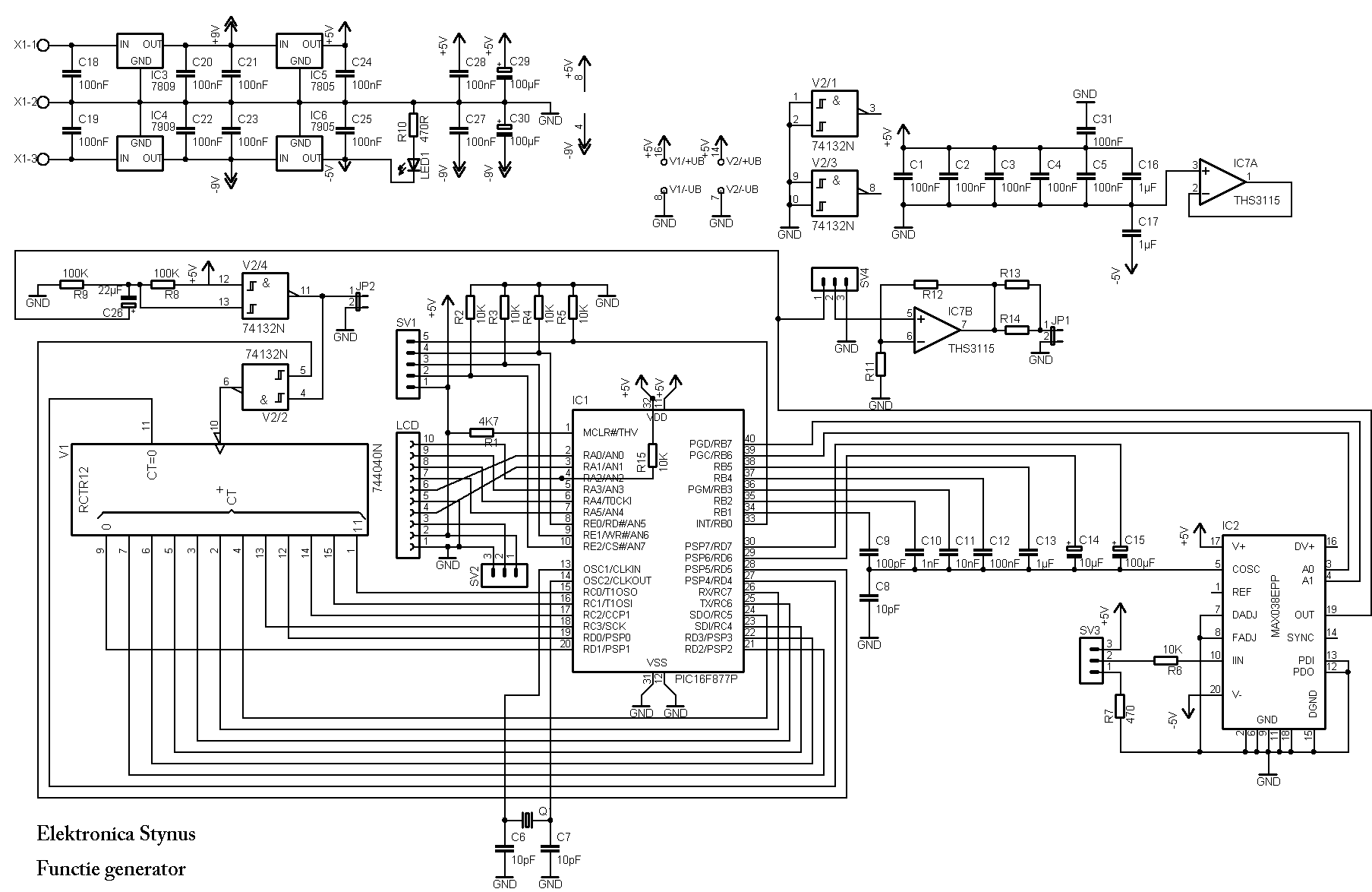
Since the last update a lot of changes happened to this project. I decided to post it when it was completely ready. I had some problems with it so that’s why it took so long before it was posted here.
At first the circuit wouldn’t work, then I found out that I’ve forgotten a resistor. After I mounted the resistor, the opamp became very hot and burned out. Probably because of oscillation. I replaced it with a opa2677 and the problems are gone.
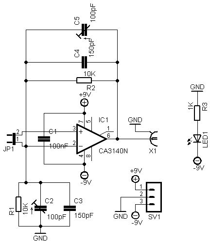
The circuit:
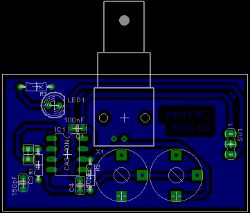
The new pcb:

I will not release this pcb layout because there are lots of bugs in it.
Build in:

New buttons:

May 23 2009
I bought a Proxxon micromot for the milling motor. The micromot doesn’t has a speed control build in, so I build one myself based on some recycled parts.

Pictures:


The Proxxon:

The clamp I made for it:

A video of the x-axis working:
I’ve got the Y axis working to but with the Z axis there is something wrong with the stepper.
May 23 2009
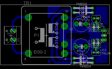
This project is a programming box with a zif socket. This way I didn’t have to build a small circuit each time I needed to program a microcontroller.
Circuit:

The pics are inserted this way:


Jun 01 2009
With this circuit you can measure on the mains with a grounded scope without tripping the rcd.
I found the circuit on Pros his site. (Link: http://prosje.be/CO/Schemas/slides/DiffProbe.html)
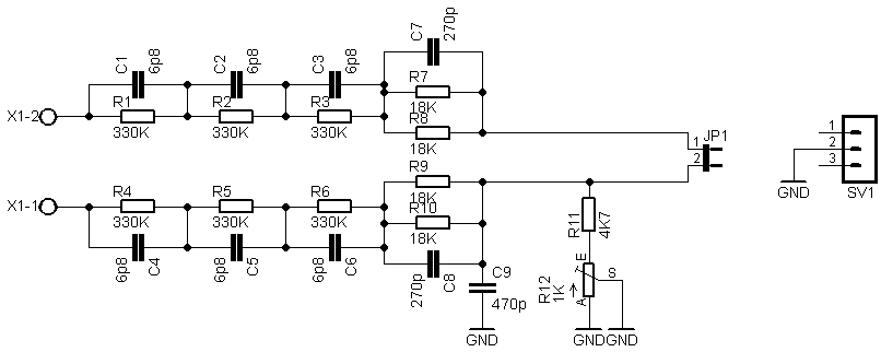
The circuit diagram’s with pcb layouts:
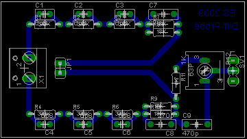
Print 1:
Print 2:
Print 3:
Pictures:


Jun 07 2009
I’m in my third year “bachelor in electronics”, so this year I have to do an internship. I decided to do that in my high school. I did this internship together with Rob. (Same rob as from the PIC controlled
robotcar)
Our assignment was to control a Yamaha servodrive for a robot arm and make this servo drive work together with a PLC that controls the rest of the machine (2 conveyor belts and 1 lift)
Working:
The robot arm should take a work piece from the storage area. Then it should place it on the top conveyor belt, that conveyor transports the work piece to the lift which brings it to the bottom conveyor belt. On the bottom conveyor belt the work piece gets drilled or stamped or similar(not part of our assignment) Then the conveyor reverses and brings it back to the lift which brings it back up and the top conveyor brings it then back to the robot arm which puts it back in the storage area.

A video of the robot arm moving. The storage area will be on the right.
Some pictures of the parts
The robot arm is being driven by this servo drive (Yamaha type QRCX-E)

The servo drive and the rest of the robot is controlled by a Siemens S7-313C PLC

The jaws of the robot:

More pictures can be found here: Link.
The report/book we wrote about this project: Link.
Jun 07 2009
We finished the safety fence


Video of the finished machine:
Jun 22 2009
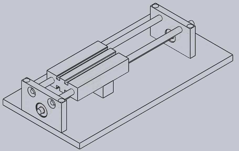
I have had a new Z-axis construction made (Thanks Jaak!). This needed to be done because the old one had 2mm of play on it. The new Z-axis is based on a compact cylinder.
Drawing:


Video of the Z-axis working:
Jul 21 2009
My new pc doesn’t have a parallel port anymore so I couldn’t use the AVR programmer I made before. That’s why I decided to build one that works on a USB port.
The design is based on the USBtinyISP design from http://www.ladyada.net/make/usbtinyisp/index.html I removed the 6p connector from the circuit because I don’t use that. And I’ve made a new print that is single sided.
The circuit drawing:

PCB layout

Pictures:


Files
PCB files as pdf: Download
Firmware: Download