Most commented posts
- Resistor Decade Box — 15 comments
- Desoldering Station — 12 comments
- 3D Printer UV Curing Device — 6 comments
- ESR-Meter – Update — 4 comments
- Dust extraction – Part 4: Solid State Relay — 4 comments
Sep 07 2008
I finished the Y-axis and made a bed from epoxy coated plywood.


I also reinforced the pillars.
Oct 11 2008
Today I made a pcb with capacitors. On the pcb I soldered 12 3300µF 100V capacitors. I bought these cheap on a radio flea market.


Oct 28 2008
I have a nas that I shut down when I go to sleep. But I noticed that it was still drawing a lot off power even in standby so I decided to build a stand-by killer. If this circuit detects that the nas draws less then a pre-set power then it shuts the output off. To eliminate measuring faults it checks during 5 seconds, if the power is low enough during these 5 seconds then it will shut down.
Circuit:
Pcb layout:


I did not like that the 220 Ohm resistor in the power supply got so hot and that there was lost to much power there. So I replaced the old power supply with a small transformer.

The box mounted and connected:


The code in the pic:
Device 12F629
Config INTRC_OSC_NOCLKOUT, WDT_OFF, PWRTE_ON, BODEN_OFF, MCLRE_OFF
ALL_DIGITAL TRUE

Symbol  GPIF        = INTCON.0
Symbol  GPIE        = INTCON.3

Symbol  GIE         = INTCON.7

Symbol  stroom      = GPIO.5
Symbol  druk        = GPIO.3
Symbol  ssr         = GPIO.2
Symbol  LED1        = GPIO.1

Symbol  LED2        = GPIO.0

Dim     index       As Byte

;         76543210
GPIO   = %00000000
TRISIO = %11111000
IOC    = %00101000
GIE    = 0         ;Global Interrupt Enable uitschakelen(!)
GPIE   = 1         ;GPIO Port change Interrupt Enable inschakelen


Clear

begin:
While 1 = 1
    GPIF = 0
    Sleep
    If druk = 0 Then
        GoTo aan
    EndIf
Wend


aan:
While 1 = 1
    High ssr
    High LED2
    GPIF = 0
    Sleep
    If stroom = 0 Then
        GoTo uit
    EndIf
    If druk = 0 Then
        GoTo af
    EndIf
Wend


uit:

While 1 = 1
    LED1 = 0
    For index = 0 To 5
        Toggle LED1
        DelayMS 500
        If stroom = 1 Then
            LED1 = 0
            GoTo aan
        EndIf
    Next
    Low ssr
    Low LED2
    GoTo begin


Wend

af:
While 1 = 1
    LED1 = 0
    For index = 0 To 5
        Toggle LED1
        DelayMS 500
        If druk = 1 Then
            LED1 = 0
            GoTo aan
        EndIf
    Next
    Low ssr
    Low LED2
    While druk = 0: Wend
    DelayMS 2000
    GoTo begin


Wend

End
Nov 02 2008
This week I have build the drivers in to the case.

I also finished the front panel.


The backpanel is almost finished.

On the right there are 3 connectors for the steppers missing. I still need to order those.
Nov 29 2008
The LEDs I used where poor quality and broke after some time. When I wanted to replace them I saw this post of vdbeke and decided to do something similar.
I used 3 pieces of PCB soldered together in a triangular form. In the side’s I’ve mounted 3 LEDs. This way I don’t have the risk of drilling in the LEDs.


Jan 19 2009
For a while the pcb from this project was laying around on my desk. Yesterday I came across it again and decided to build it in a box. I used the enclosure from an old CD-ROM player.


I didn’t feel like making a good looking front so I used a piece of pcb and coloured it red, and put a sticker on it.
Jan 25 2009
I had a few screwdrivers that weren’t magnetic anymore, and a few drills that had become magnetic (really annoying when drilling). So it was time to build a (De)magnetizer.
A while ago I had demolished 2 old speakers for parts. There were a few decent size coils in there (from the frequency filter). I have used 1 of those coils in this project

To magnetize something I connect a DC voltage to the coil. To demagnetize I connect an AC voltage.
Circuit:

I used an old bell transformer because their short circuit proof and that’s necessary because the coil has a low resistance. However the short circuit proof is limited, if you short it to long the transformer gets to hot and the thermal fuse will burn out. So you can use this device only for about 30sec (This is more than enough because it only takes about 2 seconds to magnetize something.
Some pictures:


The glue around the transformer is because the case was used for something else before.
Feb 21 2009
My galvawisp and usbwisp where too slow with bigger pics. Therefore I’ve build a new programmer. This time I have chosen for a PICkit 2. The design I based my programmer on can be found here: Link
I changed the icsp connector to a sub-d version because all my projects use this connector. And it can withstand more abuse then a pin header.
The hexfile can be found on the microchip site: Link
Circuit:

PCB:

Part list:
| Aantal: | Naam: | Waarde: |
| 2 | R1, R5 | 12k |
| 2 | R2, R6 | 4k7 |
| 2 | R3, R13 | 2k7 |
| 1 | R4 | 75R |
| 2 | R7, R8 | 33R |
| 3 | R10, R11, R12 | 680R |
| 1 | R16 | 220R |
| 1 | R17 | 1k |
| 2 | R18, R19 | 27R |
| 2 | C1, C5 | 100n |
| 2 | C2, C3 | 22p |
| 1 | C4 | 47µF |
| 1 | C6 | 10µF |
| 1 | C7 | 330nF |
| 1 | L1 | 680uH |
| 2 | D1, D2 | BAT85 |
| 1 | T1 | BC640 |
| 4 | Q1, Q2, Q4, Q6 | BS170 |
| 1 | Q5 | BS250 |
| 1 | X1 | 20MHz |
| 1 | U1 | PIC18F2550 |
| 1 | S1 | push button |
| 3 | LED1, LED2, LED3 | 3mm led |
| 1 | X2 | 15 polige sub-d |
| 1 | J1 | Wire bridge |
| 1 | CN1 | USB-B female |
Pictures:


In the enclosure:


Feb 24 2009
I got the code working. Apparently there is a bug in picbasic that gives problem with the AD on a 16F690. Therefore I made my own code to get the analogue value.
The code:
  Device 16F690
 Config INTRC_OSC_NOCLKOUT, WDT_OFF, PWRTE_OFF, MCLRE_OFF
 XTAL = 8
 OSCCON = %01110111

 Dim spanning As Word
 Dim esr As Float

 Declare LCD_DTPIN PORTC.4
 Declare LCD_ENPIN PORTC.3
 Declare LCD_RSPIN PORTB.6
 Declare LCD_LINES 2

 TRISA.2 = 1
 ADCON0 = %10000001
 ANSEL = %00000100
 ANSELH = %00000000

 ADIN_RES = 10
 ADIN_TAD = FRC
 ADIN_STIME = 500

 Symbol lcdTijd = 600
 Clear
 Cls
 Print At 1, 1, "ElektronicaStynu"
 Print At 2, 1, " ESR-Meter V1.2 "
 DelayMS lcdTijd
 Print At 1, 1, "lektronicaStynus"
 DelayMS lcdTijd
 Print At 1, 1, "ektronicaStynus."
 DelayMS lcdTijd
 Print At 1, 1, "ktronicaStynus.b"
 DelayMS lcdTijd
 Print At 1, 1, "tronicaStynus.be"
 DelayMS lcdTijd

 Cls
 Print At 1, 1, " ESR-Meter V1.2 "
 Print At 2, 1, " ESR = , "
 Print At 2, 16, $FE,$40,$00,$0E,$11,$11,$11,$0A,$1B,$00


While 1 = 1
 GoSub AD_in
 spanning = spanning - 480
 esr = spanning / 19
 If esr > 27 Then
 Print At 2, 9, "Open "
 Else
 Print At 2, 9, DEC2 esr , " "
 EndIf
 DelayMS 550


Wend
AD_in:
 ADCON0 = %10001001
 DelayMS 510
 ADCON0.1 = 1
 While ADCON0.1 = 1 : Wend
 spanning = 0
 spanning.HighByte = ADRESH
 spanning.LowByte = ADRESL


Return
End
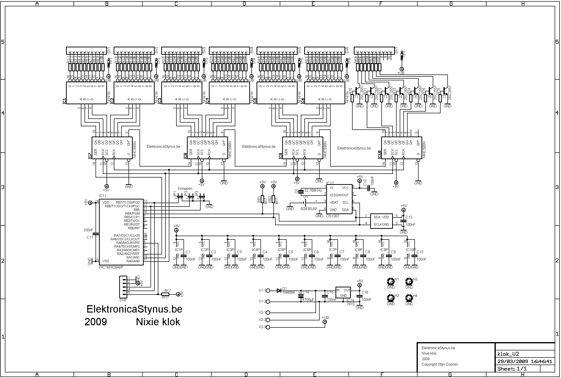
Mar 29 2009
I decided that I’m not going to wait for Robert to have time to make the code and circuit diagram any longer. So I designed something myself. The clock works with a PIC16F628A, the time is kept with a DS1307 and the temperature is measured with a TC74. I have used a couple of 74HC595 ic’s because the 16F628A doesn’t have enough IO pins. This way I create 8 outputs extra per connected 74HC595. I used those outputs to drive the nixie drive ic’s and the transistors that drive the neon’s.

Picture of the pcb:

Video of the clock working:
The code:
Device  16F628A
Config  INTRC_OSC_NOCLKOUT, WDT_off, PWRTE_off, LVP_off, MCLRE_on
ALL_DIGITAL     TRUE
PORTB_PULLUPS   = On

'In en uitgangen
    'Nixies en neons
        Symbol  klok      = PORTA.1
        Symbol  ZetVast   = PORTA.0
        Symbol  Data_Pin  = PORTA.2
    'Temperatuursensor en RTC
        Symbol  SDA       = PORTB.4
        Symbol  SLC       = PORTB.3
    'Knoppen
        Symbol  KnopR     = PORTB.7 : TRISB.7 = 1
        Symbol  KnopM     = PORTB.6 : TRISB.6 = 1
        Symbol  KnopL     = PORTB.5 : TRISB.5 = 1


'Variabelen declareren
    Dim     Teller          As Byte
    Dim     Temp1           As Byte
    Dim     Temp2           As Byte
    Dim     BCD_Opt         As Byte
    Dim     index           As Byte
    Dim     Seconden        As Byte
    Dim     Minuten         As Byte
    Dim     Uren            As Byte
    Dim     Datum           As Byte
    Dim     Maand           As Byte
    Dim     Jaar            As Byte
    Dim     Temperatuur     As Byte
    Dim     neon            As Byte
    Symbol  Reg_Seconden    =  $00
    Symbol  Reg_Minuten     =  $01
    Symbol  Reg_Uren        =  $02
    Symbol  Reg_Dag         =  $03
    Symbol  Reg_Datum       =  $04
    Symbol  Reg_Maand       =  $05
    Symbol  Reg_Jaar        =  $06
    Symbol  Lezen           =  %11010001
    Symbol  Schrijven       =  %11010000

    Clear

    While 1 = 1
        Tijd:
            For index = 0 To 50
                I2CIN  SDA, SLC, Lezen, Reg_Uren, [Uren]
                I2CIN  SDA, SLC, Lezen, Reg_Minuten, [Minuten]
                I2CIN  SDA, SLC, Lezen, Reg_Seconden, [Seconden]
                neon = %01111001

                SHOut Data_Pin, klok, msbfirst, [neon \ 8]
                DelayUS 20
                SHOut Data_Pin, klok, msbfirst, [Uren \ 8]
                DelayUS 20
                SHOut Data_Pin, klok, msbfirst, [Minuten \ 8]
                DelayUS 20
                SHOut Data_Pin, klok, msbfirst, [Seconden \ 8]
                High ZetVast
                DelayUS 20
                Low ZetVast
                If KnopR = 0 Or KnopM = 0 Or KnopL = 0 Then
                    GoSub TijdInst
                EndIf
                DelayMS 200
            Next
        Date:
            For index = 0 To 10
                I2CIN  SDA, SLC, Lezen, Reg_Jaar, [Jaar]
                I2CIN  SDA, SLC, Lezen, Reg_Maand, [Maand]
                I2CIN  SDA, SLC, Lezen, Reg_Datum, [Datum]
                neon = %01111010

                SHOut Data_Pin, klok, msbfirst, [neon \ 8]
                DelayUS 20
                SHOut Data_Pin, klok, msbfirst, [Datum \ 8]
                DelayUS 20
                SHOut Data_Pin, klok, msbfirst, [Maand \ 8]
                DelayUS 20
                SHOut Data_Pin, klok, msbfirst, [Jaar \ 8]
                High ZetVast
                DelayUS 20
                Low ZetVast
                If KnopR = 0 Or KnopM = 0 Or KnopL = 0 Then
                    GoSub DatumInst
                EndIf
                DelayMS 200
            Next
        Temp:
            For index = 0 To 10
                I2Cin SDA, SLC,$91,[Temperatuur]
                Temp1 = Temperatuur / 10
                Temp2 = (Temperatuur - (Temp1 * 10))
                Temperatuur = Temp2
                Temperatuur.7 = Temp1.3
                Temperatuur.6 = Temp1.2
                Temperatuur.5 = Temp1.1
                Temperatuur.4 = Temp1.0

                neon = %00100100

                SHOut Data_Pin, klok, msbfirst, [neon \ 8]
                DelayUS 20
                SHOut Data_Pin, klok, msbfirst, [$FF \ 8]
                DelayUS 20
                SHOut Data_Pin, klok, msbfirst, [Temperatuur \ 8]
                DelayUS 20
                SHOut Data_Pin, klok, msbfirst, [$FF \ 8]
                High ZetVast
                DelayUS 20
                Low ZetVast
                DelayMS 200
            Next
    Wend


TijdInst:
    I2CIN  SDA, SLC, Lezen, Reg_Uren, [Uren]
    I2CIN  SDA, SLC, Lezen, Reg_Minuten, [Minuten]
    I2CIN  SDA, SLC, Lezen, Reg_Seconden, [Seconden]
    neon = %01111001
    While 1 = 1
        SHOut Data_Pin, klok, msbfirst, [neon \ 8]
        DelayUS 20
        SHOut Data_Pin, klok, msbfirst, [Uren \ 8]
        DelayUS 20
        SHOut Data_Pin, klok, msbfirst, [Minuten \ 8]
        DelayUS 20
        SHOut Data_Pin, klok, msbfirst, [Seconden \ 8]
        High ZetVast
        DelayUS 20
        Low ZetVast
        DelayMS 200
        Inc Teller
        If KnopR = 0 Then
            BCD_Opt = Seconden
            GoSub bcd_tellen
            Seconden = BCD_Opt
            Teller = 0
        EndIf
        If KnopM = 0 Then
            BCD_Opt = Minuten
            GoSub bcd_tellen
            Minuten = BCD_Opt
            Teller = 0
        EndIf
        If KnopL = 0 Then
            BCD_Opt = Uren
            GoSub bcd_uur
            Uren = BCD_Opt
            Teller = 0
        EndIf
        DelayMS 250
        If Teller = 12 Then Break
    Wend
    'Wegschrijven
    I2COUT SDA, SLC, Schrijven ,Reg_Seconden, [Seconden]
    I2COUT SDA, SLC, Schrijven ,Reg_Minuten, [Minuten]
    I2COUT SDA, SLC, Schrijven ,Reg_Uren, [Uren]


Return
bcd_tellen:
    Temp1 = BCD_Opt & %00001111 'Xor
    Temp2 = BCD_Opt - Temp1
    Temp2 = Temp2 >> 4
    Inc Temp1
    If Temp1 > 9 Then
        Temp1 = 0
        Inc Temp2
        If Temp2 > 5 Then
            Temp2 = 0
        EndIf
    EndIf
    Temp2   = Temp2 << 4
    BCD_Opt = Temp2 + Temp1


Return
bcd_uur:
    Temp1 = BCD_Opt & %00001111 'Laagste bits doorlaten
    Temp2 = BCD_Opt - Temp1
    Temp2 = Temp2 >> 4
    Inc Temp1
    If Temp1 > 9 Then
        Temp1 = 0
        Inc Temp2
        If Temp2 > 5 Then
            Temp2 = 0
        EndIf
    EndIf
    Temp2   = Temp2 << 4
    BCD_Opt = Temp2 + Temp1
    If BCD_Opt > 23 Then
        BCD_Opt = 0
    EndIf
Return


DatumInst:
    I2CIN  SDA, SLC, Lezen, Reg_Jaar, [Jaar]
    I2CIN  SDA, SLC, Lezen, Reg_Maand, [Maand]
    I2CIN  SDA, SLC, Lezen, Reg_Datum, [Datum]
    neon = %01111010
    While 1 = 1
        SHOut Data_Pin, klok, msbfirst, [neon \ 8]
        DelayUS 20
        SHOut Data_Pin, klok, msbfirst, [Datum \ 8]
        DelayUS 20
        SHOut Data_Pin, klok, msbfirst, [Maand \ 8]
        DelayUS 20
        SHOut Data_Pin, klok, msbfirst, [Jaar \ 8]
        High ZetVast
        DelayUS 20
        Low ZetVast
        DelayMS 200
        Inc Teller
        If KnopR = 0 Then
            BCD_Opt = Jaar
            GoSub bcd_jaar
            Jaar = BCD_Opt
            Teller = 0
        EndIf
        If KnopM = 0 Then
            BCD_Opt = Maand
            GoSub bcd_Maand
            Maand = BCD_Opt
            Teller = 0
        EndIf
        If KnopL = 0 Then
            BCD_Opt = Datum
            GoSub bcd_Datum
            Datum = BCD_Opt
            Teller = 0
        EndIf
        DelayMS 250
        If Teller = 12 Then Break
    Wend
    'Wegschrijven
    I2COUT SDA, SLC, Schrijven ,Reg_Jaar, [Jaar]
    I2COUT SDA, SLC, Schrijven ,Reg_Maand, [Maand]
    I2COUT SDA, SLC, Schrijven ,Reg_Datum, [Datum]


Return
bcd_jaar:
    Temp1 = BCD_Opt & %00001111 'Xor
    Temp2 = BCD_Opt - Temp1
    Temp2 = Temp2 >> 4
    Inc Temp1
    If Temp1 > 9 Then
        Temp1 = 0
        Inc Temp2
        If Temp2 > 9 Then
            Temp2 = 0
        EndIf
    EndIf
    Temp2   = Temp2 << 4
    BCD_Opt = Temp2 + Temp1


Return
bcd_Maand:
   Temp1 = BCD_Opt & %00001111 'Laagste bits doorlaten
    Temp2 = BCD_Opt - Temp1
    Temp2 = Temp2 >> 4
    Inc Temp1
    If Temp1 > 9 Then
        Temp1 = 0
        Inc Temp2
    EndIf
    Temp2   = Temp2 << 4
    BCD_Opt = Temp2 + Temp1
    If BCD_Opt = $13 Then
        BCD_Opt = 1
    EndIf
    If BCD_Opt = 0 Then
        BCD_Opt = 1
    EndIf
Return


bcd_Datum:
   Temp1 = BCD_Opt & %00001111 'Laagste bits doorlaten
    Temp2 = BCD_Opt - Temp1
    Temp2 = Temp2 >> 4
    Inc Temp1
    If Temp1 > 9 Then
        Temp1 = 0
        Inc Temp2
    EndIf
    Temp2   = Temp2 << 4
    BCD_Opt = Temp2 + Temp1
    If BCD_Opt = $32 Then
        BCD_Opt = 1
    EndIf
    If BCD_Opt = 0 Then
        BCD_Opt = 1
    EndIf
Return
End
The hex file: Link.
The next step is making the case. But this may take a while.