After the electronics from my first nixie clock where ready, I wanted to build a second one. It took some time, but a few weeks ago I bought some IN-14 nixies.
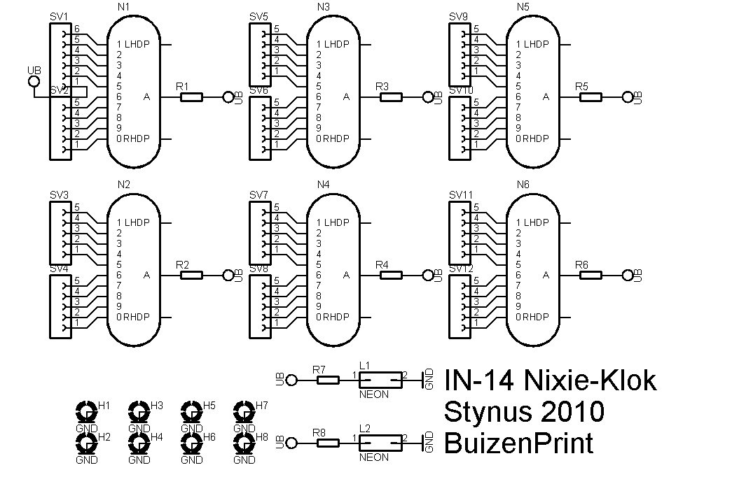
The circuit is roughly the same, only I tried to make it as compact as possible. The complete clock consists of 3 stacked pcb’s. On the bottom pcb is the high voltage supply, the 5V supply, the pic, the rtc and the temperature sensor. On the middle pcb are the 74141 nixie drivers and 74HC595 shift registers. On the top print are the nixies and neon’s.
 |
 |
 |
This time I used leds to indicate which data is on the nixies (time, date or temperature). This way I can save a lot of pcb space.


I’m basing the enclosure on the Ice Tube Clock from Adafruit:

Display test:
Clock ready:
2 comments
Hello
I come on you site and saw the scheme and I think it’s possible to do for me. And the Nixie tubes have I also. I have the IN-8 but how I read it ist the same tension that’s comes on the tubes. bBut what I want to ask you is if have to programing something for that’s and if yes than with which programm and if I could have the programing code. And if it’s possible a list with the parts that I need to do it. And I want to excuse me in advance for the mistakes.
greetings from switzerland
Author
Hello,
The code can be found in the last post of this series. https://en.elektronicastynus.be/category/projects/clocks/in-14-nixie-clock/
The program used to compile the code is proton picbaisc. A part list is also on the page.
Regards,
Stijn