Most commented posts
- Resistor Decade Box — 15 comments
- Desoldering Station — 12 comments
- 3D Printer UV Curing Device — 6 comments
- ESR-Meter – Update — 4 comments
- Dust extraction – Part 4: Solid State Relay — 4 comments
Jul 03 2008
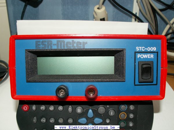
Some time ago I came across this design of an ESR meter. I then decided to build it, but for the display I wanted to use a pic + lcd.
My circuit:

(Clickable)
Pictures:


Jul 10 2008
I decided to build a enclosure myself because the old enclosure above is not pretty enough. I’m also going to replace the heat sink by 2 larger ones that I bought on a radio market.
The heat sinks will form the side’s of the new enclosure. The rest will be made from aluminium sheet.

Jul 10 2008
The past 2 weeks I’ve been busy finishing the second pcb and the housing.
I made a time-lapse from the soldering:
To make it look professional I made some stickers for on the side’s.

The sticker as pdf: Link.
Today I got my milk-glass and mounted it.


Jul 17 2008
I bought some bigger heat sink for cheap. (Thanks Ben and Robert). I have put those new heat sinks on this power supply. With this heat sink it doesn’t need a fan, because the ribs run in the other direction and the heat sink is much bigger. I cut 5cm of the case at the back and mounted the heat sinks. In the middle I’ve put a panel for the power connector and in the future a usb connector.


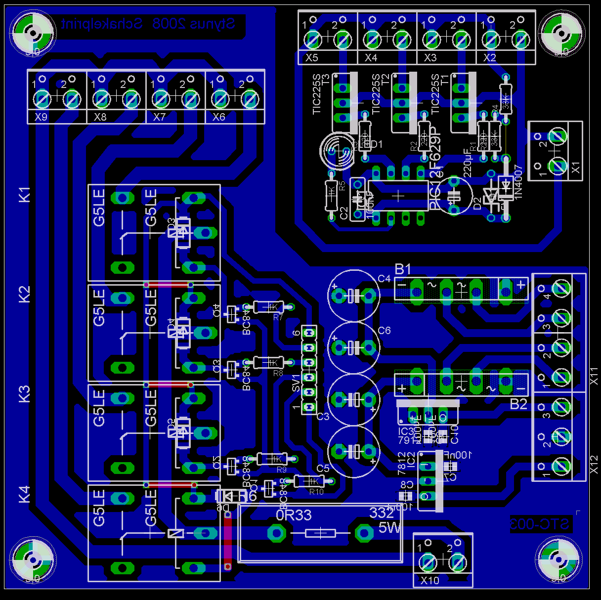
I also made a new switch pcb because I was not happy anymore with the old design. The triacs to switch the 230V side of the transformers are driven by an PIC12F629. I have put a low power powersupply on this pcb to generate 2*5V from the extra windings I made around the transformers.

Partlist:
| R1, R2, R3 | 220R |
| R4, R11 | 33K |
| R6 | 0R33 5W |
| R5 | 3K3 |
| R7, R8, R9, R10 | 1K |
| C1 | 470µF 25V |
| C2 | 100nF |
| C3, C4 | 10µF 25V |
| C5, C6 | 1000µF 25V |
| C7, C8, C9, C10 | 100nF SMD 0805 |
| D1 | 1N4007 |
| D2 | 5V1 |
| D3, D4, D5, D6 | 1N4007 SMD |
| B1, B2 | rectifier |
| IC1 | PIC12F629 (Code) (Hex) |
| IC2 | 7812 |
| IC3 | 7912 |
| K1, K2, K3, K4 | Relays |
| LED1 | LED 5MM red |
| Q1, Q2, Q3, Q4 | BC848 SMD |
| T1, T2, T3 | TIC206D |


Jul 22 2008
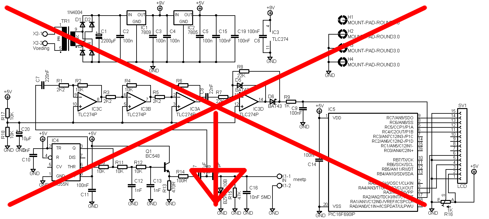
I made a mistake in my circuit. The non inverting inputs off the opamp should be connected to 2,5V instead of the ground. I could make a new pcb, but I decided to make it myself easy and made a special ic socket with a voltage divider build in.


The new circuit diagram:
Jul 29 2008
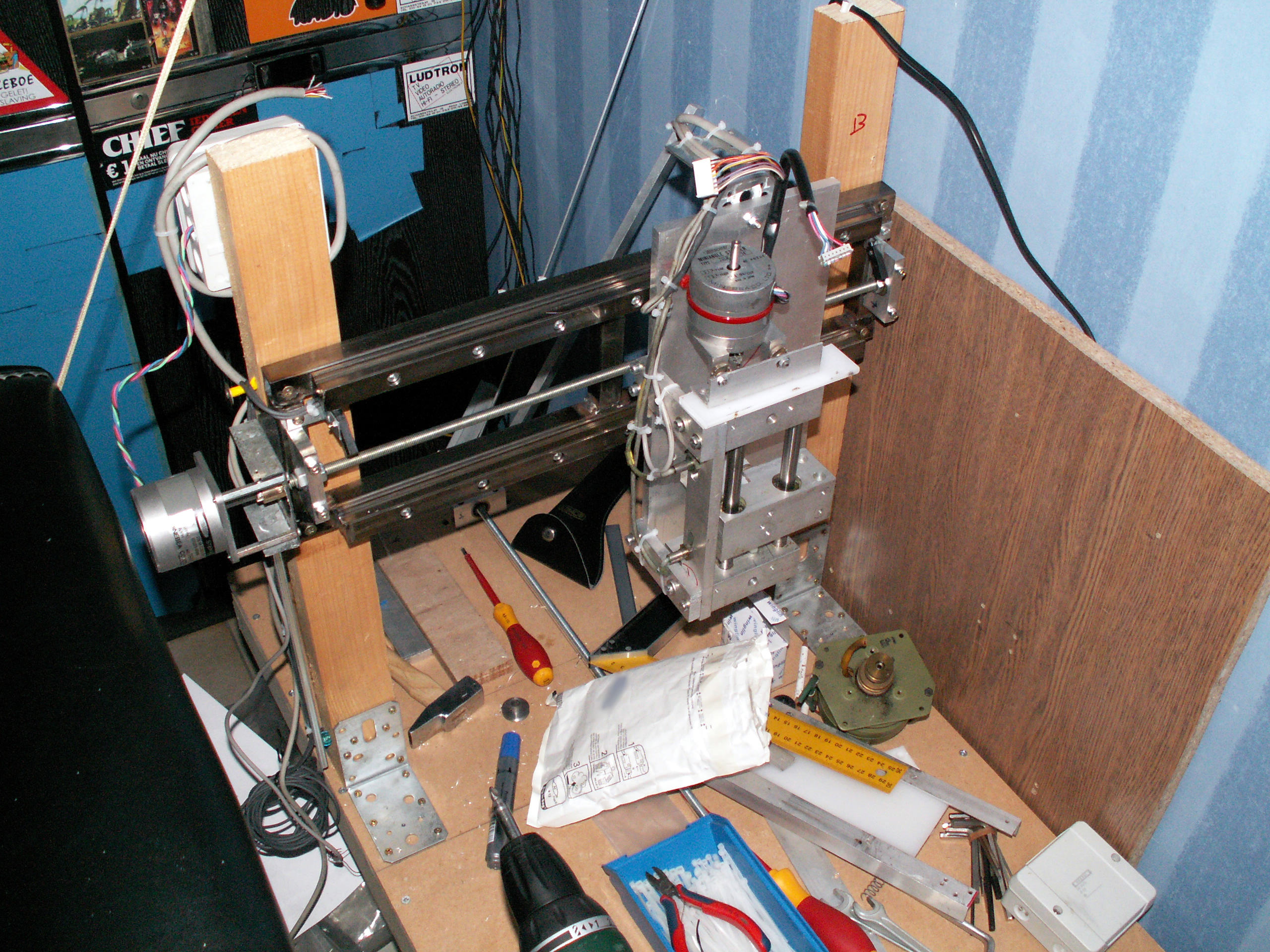
I have received another set of bearing holders (Thanks Jaak!!). Yesterday I mounted 2 off them at the Y-axis and I made another nut from plastic. I also made a bracket from some scrap rvs to mount the stepper. The coupling with the spindle is made from a piece of scrap brass with some bolts.

To protect the axis I’ve put some inductive end sensors on it, and on the back I’ve made a cable duct for the cables from the Z-axis.

Aug 21 2008
I made another 2 stepper drivers:
Yesterday I made a new motherboard. The old 1 had a few design flaws in it. The new one is for 4 axis so I don’t need to build another one if a forth axis is added.
Circuit:

Pcb:

Partlist:
|
Name:
|
Value:
|
|---|---|
| R1, R2, R3, R4 | 4K7 |
| R5, R6, R7, R8, R9, R10, R11, R12 | 470R |
| R13, R14, R15, R16 | 330R |
| R17, R18, R19, R20 | 3K3 |
| C1 | 4700µF |
| C2, C3 | 100n |
| D1, D2, D3, D5 | 1N4004 |
| IC1 | ULN2803 |
| IC2 | 7805 |
| LED1, LED2, LED3, LED4, LED5, LED6, LED7, LED8 |
LED groen 5mm |
| LED9, LED10, LED11n LED12 | LED rood 5mm |
| OK1, OK2, OK3 | PC849 |
| TR1 | Transformer 1.5VA 9-20V |
| X1 | 25p sub-d connector |
| X2, X3, X4, X5 | 3p printkroonsteentje |
| X6 | 5p printkroonsteentje |
| X10 | 2p printkroonsteentje 230V |


Aug 26 2008
After my 7805 of my previous breadboard power supply was broken because of a to small heat sink, I decided to build a new version. This new version also delivers 12V. Both voltages can deliver 0.5A.
The case is from a cheap pc power supply.
Circuit:

Pictures:


Aug 29 2008
Because a usb->serial converter coupled takes a lot of space, I’ve decided to build a wisp programmer with a build in converter. I used a ft232 for this job. With the jumper on the pcb I can choose between “target powered” and “usb powered”.
The circuit:

The pcb layout:

Silkscreen-bottom pdf: Link
Copper-bottom pdf: Link
Copper-top pdf: Link
Silkscreen-top pdf: Link
Pictures:


Part list:
| R1 | 4k7 0805 |
| R2 | 10k 0805 |
| R3, R9, R10, R12 | 1k 0805 |
| R4, R5, R6, R7, R8, R11 | 47R 0805 |
| C1, C2, C3, C4 | 100n 0805 |
| C6, C7 | 22pF 0805 |
| C8, C9 | 1µF 0805 |
| C10 | 22µF |
| C11 | 100µF |
| D1, D2, D3 | BAT85 |
| D4 | SB140 SMD |
| D5 | 1N4148 |
| IC1 | FT232RL SSOP28DB |
| IC2 | PIC16F648A SO-18W |
| JP1 | 3p JUMPER |
| L1 | INDUCTOR 0603 |
| LED1 | LED 3MM Red |
| LED2 | LED 3MM Green |
| Q1 | 20Mhz kristal |
| Q2 | BC847 SOT23 |
| SV1 | 5P female header |
| X1 | USB MINI connector |
| X2 | 15p male sub-d |
The hex file for the pic can be found here: http://www.voti.nl/wisp648/
Sep 06 2008
I designed the pcb for the stepper driver. It uses an L297 and L298 ic. The circuit I used:

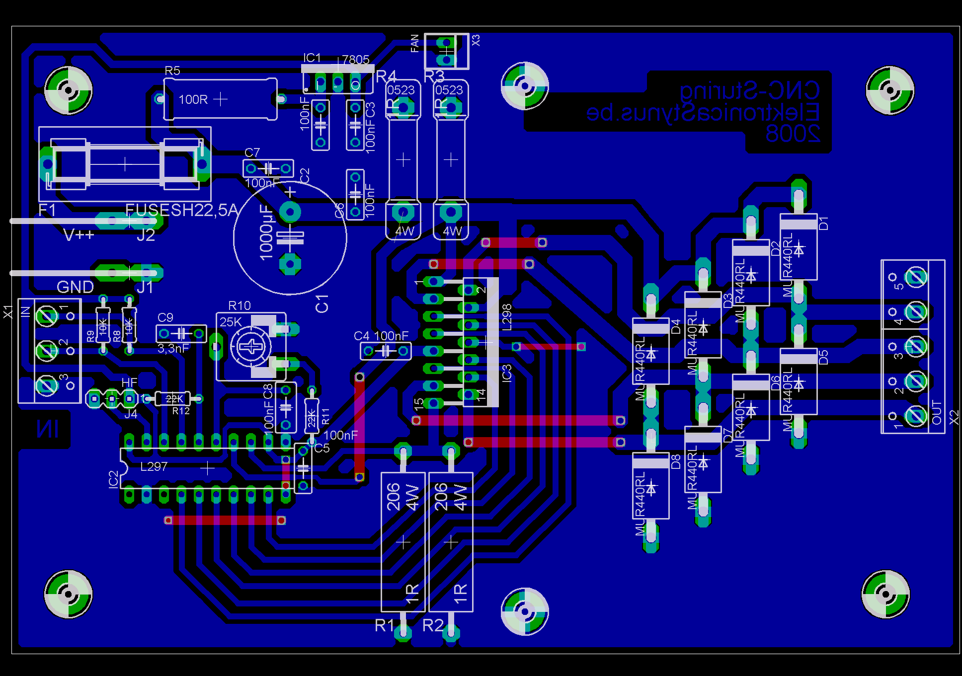
Partlist:
|
Name:
|
Value:
|
|---|---|
| R1, R2, R3, R4 | 1R 3W |
| R5 | 100R 5W |
| R8, R9 | 10K |
| R10 | 25K trim potmeter |
| R11, R12 | 22K |
| C1 | 1000µF 50V |
| C2, C3, C4, C5, C6, C7, C8 | 100nF |
| C9 | 3,3nF |
| D1, D2, D3, D4, D5, D6, D7, D8 | MUR440RL |
| IC1 | 7805 |
| IC2 | L297 |
| IC3 | L298 |
| J1, J2 | AMP vlakstekker |
| J4 | 3p pin header |
| X1 | 3p printkroonsteen |
| X2 | 5p printkroonsteen |
| X3 | fan connector |
| F1 | 4A fuse + holder |
| M1 | 40mm 5V Fan (optional) |


