Most commented posts
- Resistor Decade Box — 15 comments
- Desoldering Station — 12 comments
- 3D Printer UV Curing Device — 6 comments
- ESR-Meter – Update — 4 comments
- Dust extraction – Part 4: Solid State Relay — 4 comments
Oct 19 2014
A while ago I decided to convert my AMA-16 milling machine to cnc. For this machine I bought some stepper drivers to save the time of building them myself. I have mounted these drivers together with some power supplies and relays in a control box. Unfortunately I have not made many pictures during the build process.
Pictures:


Bottom side vent openings:

There are 3 ventilation openings on top. I protected these with air filters to keep out the dust.

The stepper motors are connected to the control box via speakon connectors:


Interface board:

On/off switch


Control circuit:

Sensor, power and control inputs:

I have mounted a touch-screen to the front of the control box.

More info will follow in a future update.
Dec 21 2014
Today there was a Radio flea market in Bladel. What I bought (for 15€ including entrance fee):
2x CCD camera
1x Bag earth screw rails1x Bag euro connectors Male
2x Bag flat flex cables
1x Bag push-buttons
1x 40mm fan
10x Switch

May 17 2015
Today there was a Radio flea market in Eksel.
What I bought (for 34€ including entrance fee):
-6x bags connectors
-8x drawer slides
-1x 717W server power supply

May 01 2016
Today there was a Radio flea market in Diest.
What I bought (for 9€ including entrance fee):
-3x bag brass thick washers
-1x 10 turn potmeter
-1x bag connectors
-1x bag springs

May 31 2017
The last few years I did not post a lot. This while I did made a lot of projects. The biggest reason for this is that I had to do all the updates in HTML code. This took a lot of time and to me is very boring. This caused me to not feel like updating the site. Therefore I now changed everything over to WordPress which makes it easier to update.
The comments unfortunately could not be imported from the old site.
Jul 28 2017
Previous part of this project: Link
On the CircuitsOnline forum there was an action to buy power supply boards. At this action I bought 2 boards. When I was looking for an enclosure to use for this project I came across this old project and decided to use the enclosure for the new power supply.
For this design other auxiliary power supplies are needed than with the previous design. Therefore I made some new boards:
1x 2x9V AC psu to power the drive circuit and fan
2x 5V DC to power the V and A meter
1x board with big capacitors
Total overview with all boards:


After a few tests, it turned out that the heatsink became too hot. To solve this a fan was added.

This fan is controlled by temperature. This control is based on a MCP9701T sensor with a PIC16F527 micrcontroller.
The board of the fan controller:

Fan controller XC8 source code + hex download
The finished result:


Aug 05 2017
A few years ago I bought a second-hand Systron Donner HR 70-3AI power supply. This power supply works with a pre-regulation by “dimming” the transformer to limit the power dissipation. This works ok, but the psu has a rather big output capacitor (3300µF), which makes it unsuitable for testing circuits.

After a few months the psu broke down, and instead of fixing it I decided to upgrade it by adding a new lab power supply part. For this I used a board I got from an action on circuitsonline. The heat sinks are rather small and can not handle the 210W (70V x 3A), therefore I decided to reuse the pre-regulation and have it regulate about 10V above the output voltage. For this I designed an interface circuit.
Old power supply drive board / pre-regulation driver:

New lab power supply circuit:
Interface circuit rev 1:

Interface circuit rev 2:

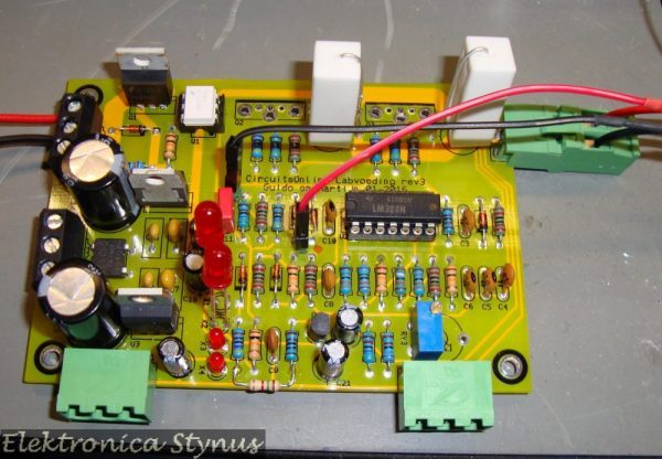
Interface circuit rev 3:

Circuit diagram:

The boards mounted:

Other alterations that have been done on the power supply:
The new output cap:

Total overview:

On the outside nothing has been changed to the enclosure.

Aug 11 2017
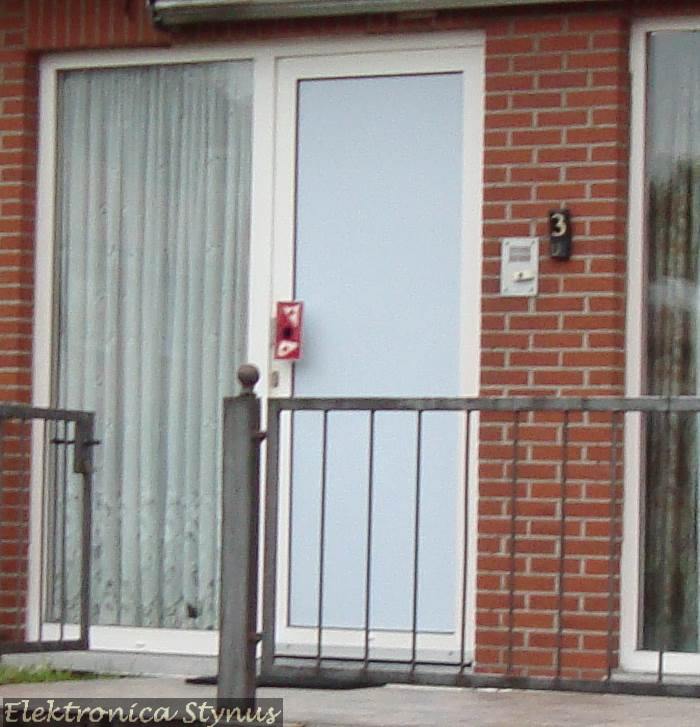
When I bought my house there was a wireless push-button for the doorbell, this was mounted on top of an old door intercom system. Because the plate is metal, it acted as a shield making the wireless door bell not work very well. Next to this was an plastic house number that was cracked all over from the sun UV light.
Time to make something new, and off course I made it a bit overkill.
The old situation:
I drew a design for an stainless steel plate. This plate contains the house number, a hole for the push button, and 4 mounting holes. This design I had lasered by RoboCNC.

A piece of smoked PMMA plastic will be mounted behind this plate. It will be illuminated by a LED board:

This board has 3 modes:
The lights are switched on / off with an build in twilight switch.
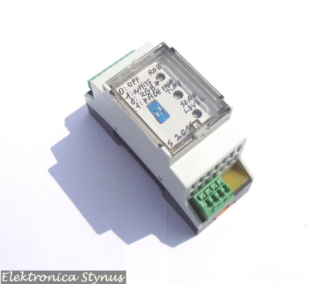
It is not convenient to change the mode on the build in board. Therefore I made a “remote controll” that will be mounted in the house fuse box on a din rail.


LED board mounted:

Finished:

The din rail module in the fuse box:

Circuit diagrams:


Downloads:
PCB files: Link
XC8 code: Link
Aug 28 2017
When I etch my own circuit boards, sometimes it happens that there is a very small short on the board. This short is difficult to find. To burn this short away it is handy to have a power supply that can deliver lot of current. My heaviest lab supply however can only supply 6A. Therefore I made this project:
This project is a 5V power supply with an adjustable current limit up to 30A. This power can not be outputted continuously. To make the 5V I used an old ATX PC power supply, these can supply a lot of current on the 5V line.


I have put 12 high power transistors on the secondary side of the power supply to regulate the voltage/current. The transistors are mounted to actively cooled heat sinks. 2 extra power transistors are added to drive the other transistors.

The heat sinks are from 2 old Pentium 2 processors. On top I put a few fans.

I found a few LCD voltmeters in my junk supply. These I have used in this project as volt and ampere meter.
Test layout:

Mounted:

With the switch the output can be enabled. The switch has 3 positions:
-Neutral position = OFF
-Spring return position = output on as long as the switch is activated
-Latch position = output permanent on
The 2 panel meters need their own power supply (isolated voltage), this I solved by adding a small transformer followed by 2 7805 regulators.

This part is the drive circuit of the transistors. This also include the current measurement:
Circuit:

The big pile of resistors are used because the power in the resistors at these currents is very high. I could have used a lower resistance value, but I did not have that in stock. From these resistors I had a partial reel (SMD).


PCB build in:


Ready:


Sep 11 2017
Some time ago I bought a Mantis microscope for cheap at an auction.
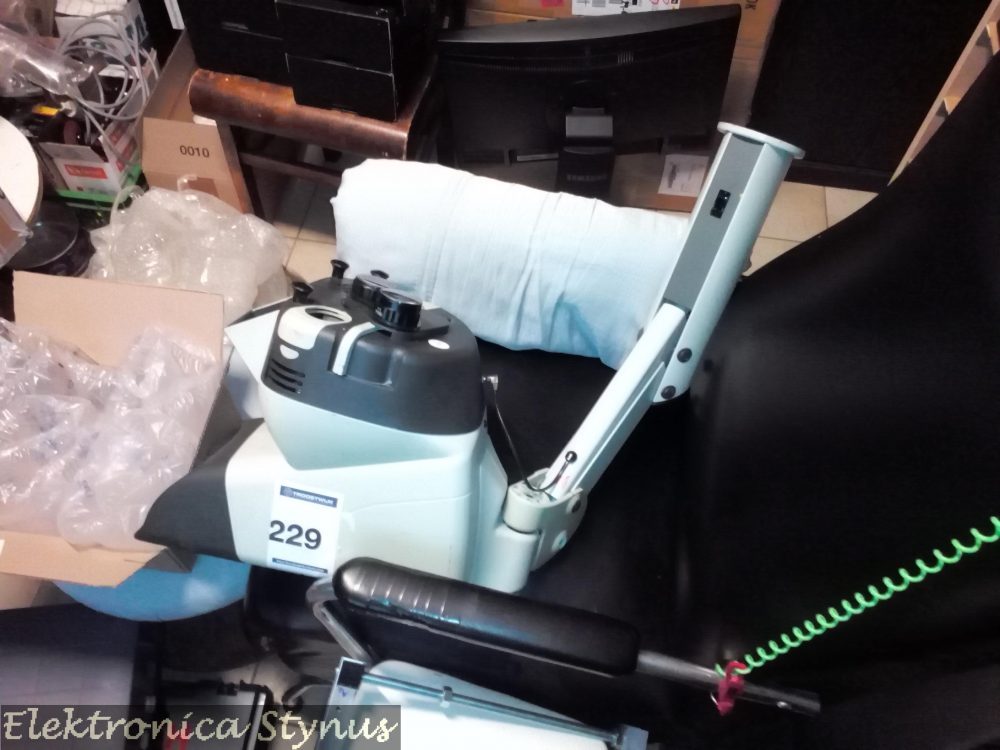
The reason why it was cheap was that the base was not included. Therefore I designed a new base and 3D printed it. The base is printed from PETG and has a M10x50 bolt + nut to reinforce it.

The bottom of the microscope:

Print without bolt:
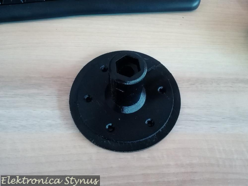
With bolt:


Mounted:


Please accept YouTube cookies to play this video. By accepting you will be accessing content from YouTube, a service provided by an external third party.
If you accept this notice, your choice will be saved and the page will refresh.
Downloads:
–STL File