Most commented posts
- Resistor Decade Box — 15 comments
- Desoldering Station — 12 comments
- 3D Printer UV Curing Device — 6 comments
- ESR-Meter – Update — 4 comments
- Dust extraction – Part 4: Solid State Relay — 4 comments
Oct 03 2017
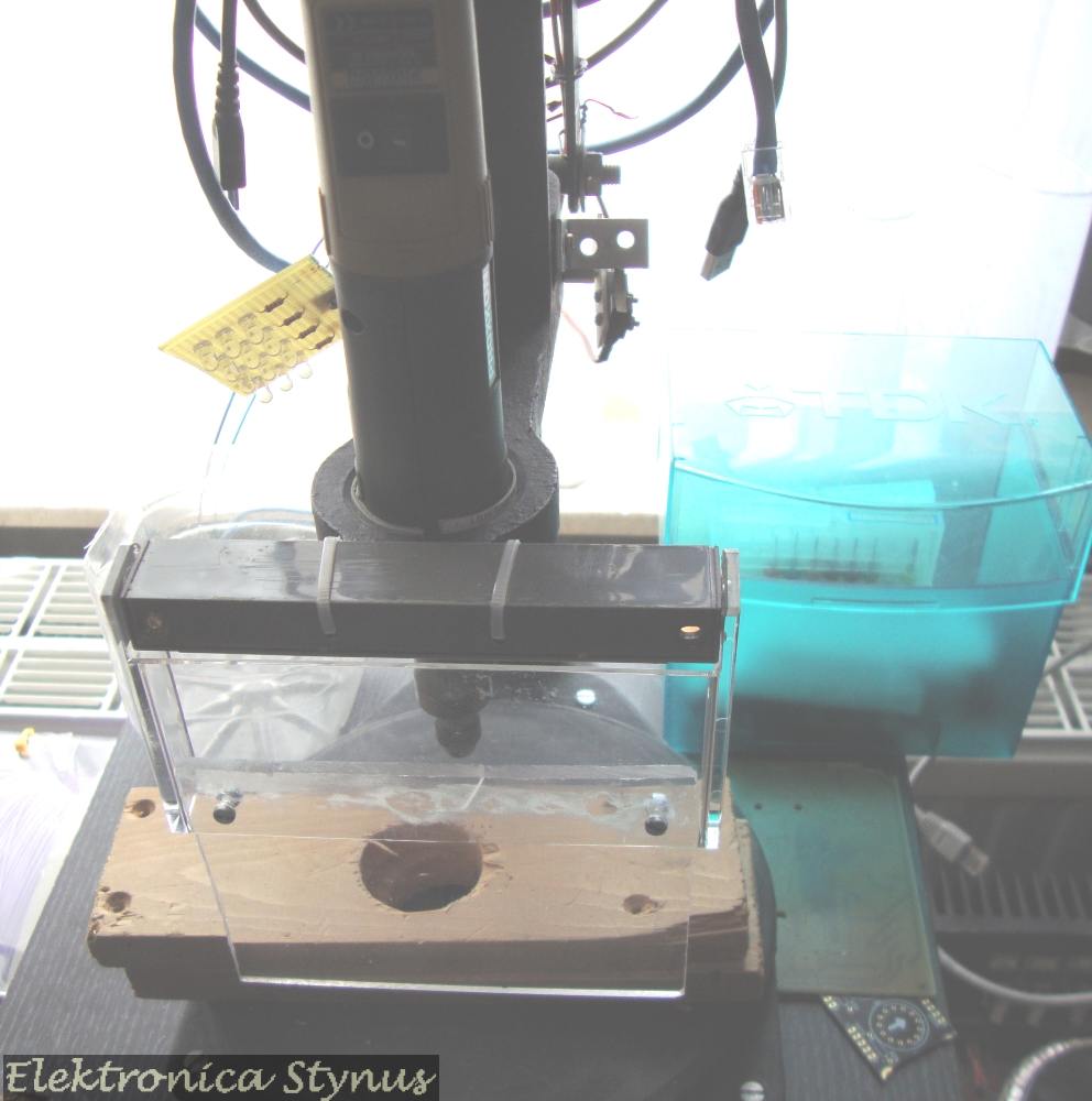
In the pictures in the previous update a cd case is used as a safety glass in front of the drill. This is rather thin, therefore I decided to exchange it to 4mm plexiglas. This new plexiglas is hinged by the cover of an old tape deck.
Old situation:

New situation:
Dec 17 2017
Today there was a Radio flea market in Bladel. What I bought:

Dec 28 2017
I needed a acrylic plate that is 90cm long and is bend 90° over the ling side. For this I requested some quotes from various suppliers. They all came in at about €100 to do this. Therefore I decided to invest the €100 in a DIY bending jig, this way I can also use it in future projects.
After some searching in my scrap-parts bin I came across a heater resistor from a clothes dryer.

I cut of the ceramic isolators and mounted the resistor wire between 2 screws. Around this I build the bending part. This consists of a fixed board and a board on hinges.
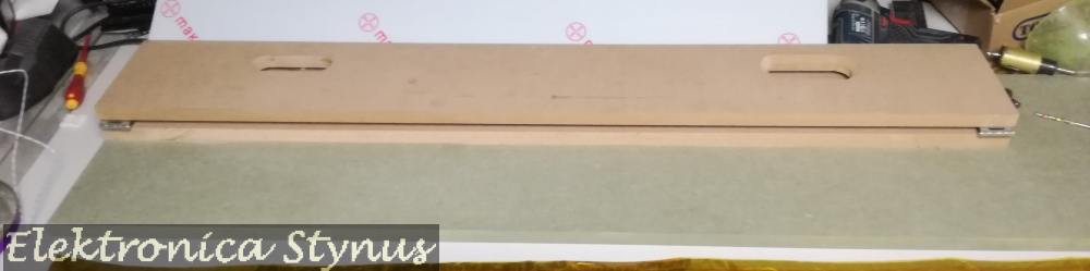
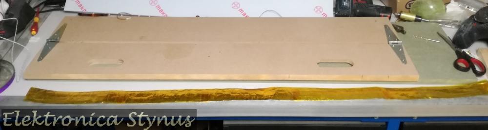
I added some aluminium foil that is covered with a layer of kapton isolaton tape to protect the wood against the heat

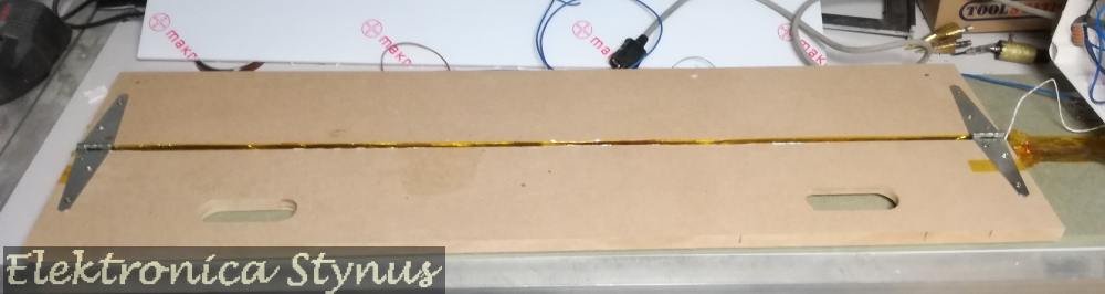
An extra board is screwed on top to fix the acrylic sheet.
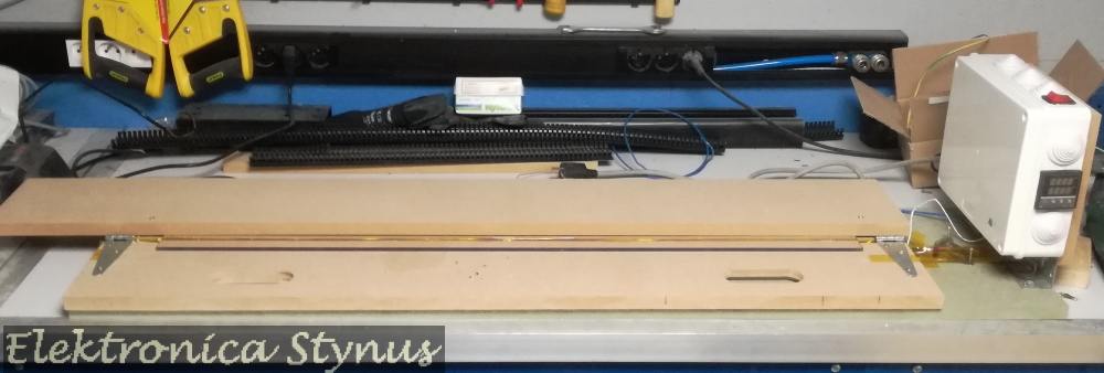
The device can be used like this, however it gets too hot and may discolour/warp the plastic. Therefore I added an PID controller to control the temperature of the wire. In the center I stuck a thermocouple sensor to the resistance wire.
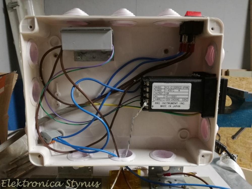
The messy inside of the controller box:

A videoclip of the bender with a polycarbonate plate:
(I also heated from the top with a heat gun, this to get it hot faster. This may not be necessary, however I have not tested yet without this.
The result:
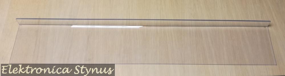
When copying this design please not that the resistor wire is connected to mains, and therefore is not safe. To use this more safe a isolation transformer is recommended.
Components used:
Mar 04 2018
Today there was a Radio flea market in Helchteren. What I bought:

Apr 27 2018
Some time ago I bought a lot of Weller soldering irons at an auction for cheap. Between these where a few DSX 80 de-soldering irons.

I also had an old Weller IG101 solder station (bought earlyer from another hobbyist), unfortunately I had no iron for this one and the DSX 80 could not be connected to this one. Time to convert the IG101 to newer standards.
IG101 station:

To use this station a few alterations where required. Most important is that it is 24V input, I want to change this to 230V. Also I did not like the connection for the vacuum to be on the side of the unit, so I moved it to the front (same as the modern units). The vacuum is created by a venturi valve, the air output of this valve is still on the side, since the enclosure was too small for another bend.
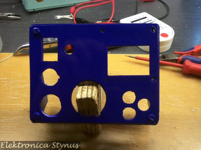
First I closed the old holes for the air connections and added a cut-out for a 230V power connector. The cover will later be painted making these “fixes” invisible.

I placed the valve on the bottom of the enclosure. On top of the valve a metal plate to mount the toroid transformer (2x12V 100VA)
Next the front panel was changed to incorporate the vacuum connection, Nokia 5110 LCD and buttons.
The old electronics where replaced with a new board driven by a PIC microcontroller.
Old:
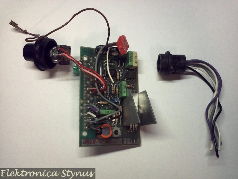
New:


Circuit diagram:

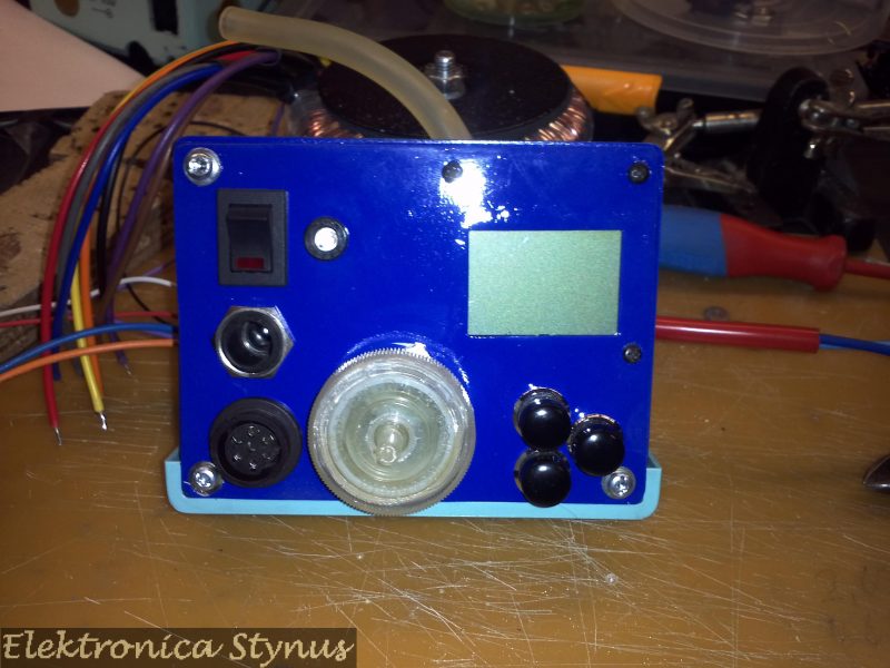
The finished result:


Mounted next to a standard solder station:

In use:
Firmware: Link
May 05 2018
Today there was a Radio flea market in Neerpelt. What I bought:

Jun 17 2018
Today there was a Radio flea market in Diest.
What I bought:


Jun 23 2018
I was curious about the insides of the TC08 thermocouple logger that I bought at the radio flea market in Diest. Therefore I took it apart and made some pictures:


Sep 02 2018
In a lot of electronics I bought there was a small variac. Unfortunately I could not find a datasheet, but after some experimentation I found out it was for 12V AC. Laying on the shelve it was quite useless, so I decided to make an low voltage AC power supply with it.

To determine the max input voltage, I measured the zero load current and put it with the input voltage in a graph:

From this graph I concluded that as long I stay below 15V saturation is not a problem. Therefore I have chosen to use it on 12V.
I build it in enclosure together with an 12V halogen transformer. Also I readout based on that of my Safety transformer V2 & Safety transformer V3, the version in this project however is adapted to measure lower voltages, so the resolution increases. Also a power supply for the meters is added.

Complete unit:


Oct 07 2018
My new workshop is in my basement. For the hand washing / board cleaning “corner” this has the disadvantage that it is below the sewage level. In order to drain the water it needs to be pumped up. I had a few pumps from old washing machines laying around and decided to do some experimentation with this.
To make it easier for the pump (and to spare my back) I made a frame underneath the cabinets to raise the whole thing by 20cm. This way the water needs to be lifted less.

Normally there is a siphon after the drain in the sink, this part I have taken out and brought the pipe directly to the pump.

At the pump side the pipe goes down a bit in order to make the check valve work better (Picture further down on the page). Also because of this the sensor is not mounted at the lowest point. This makes it work better since the pump does not clear all the water from the pipes. The water that does stay in the pipe may false trigger otherwise.
However this means that the pump needs to operate longer when the sensor signal go’s off. Therefore I made a timer box. This was made with a Siemens LOGO The time is settable by a rotary switch. This switch is connected with a few inputs of the LOGO.
The pump:

The timer box:


The program in the LOGO!:

To detect the water in the pipe I used a E2K-L26MC1 capacitive sensor from Omron. This sensor can be clamped around the pipe and does not come into contact with the water.
The sensor cheapest supplier for this sensor, I found on AliExpress.com: – Omron Level Sensor E2K-L26MC1

This sensor has an NPN output, while the LOGO is only compatible with PNP output sensors. This I solved by adding a 10K pull-up resistor between out and +24V. After this the input needs to be inverted in the LOGO to work correctly (B17 in the program above).
Picture of the box and sensor installed:
