Category: Uncategorized

70V 3A Lab Power Supply Upgrade

A few years ago I bought a second-hand Systron Donner HR 70-3AI power supply. This power supply works with a pre-regulation by “dimming” the transformer to limit the power dissipation. This works ok, but the psu has a rather big output capacitor (3300µF), which makes it unsuitable for testing circuits.

After a few months the psu broke down, and instead of fixing it I decided to upgrade it by adding a new lab power supply part. For this I used a board I got from an action on circuitsonline. The heat sinks are rather small and can not handle the 210W (70V x 3A), therefore I decided to reuse the pre-regulation and have it regulate about 10V above the output voltage. For this I designed an interface circuit.

Old power supply drive board / pre-regulation driver:

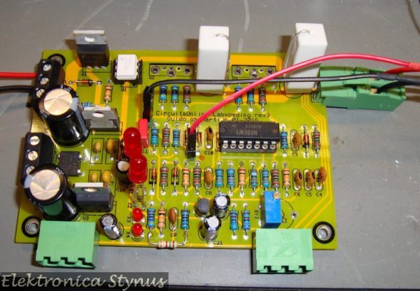
New lab power supply circuit:

Interface circuit rev 1:

Interface circuit rev 2:

Interface circuit rev 3:

Circuit diagram:


The boards mounted:

Other alterations that have been done on the power supply:

  • The power transistors have been changed to transistors of the MJ11016 type
  • An extra 2x9V AC PSU has been added
  • The output capacitor has been changed from 3300µF to 150µF
  • The potentiometers are changed to different values.

The new output cap:

Total overview:

On the outside nothing has been changed to the enclosure.


Drain pump system

My new workshop is in my basement. For the hand washing / board cleaning “corner” this has the disadvantage that it is below the sewage level. In order to drain the water it needs to be pumped up. I had a few pumps from old washing machines laying around and decided to do some experimentation with this.

To make it easier for the pump (and to spare my back) I made a frame underneath the cabinets to raise the whole thing by 20cm. This way the water needs to be lifted less.

Normally there is a siphon after the drain in the sink, this part I have taken out and brought the pipe directly to the pump.

At the pump side the pipe goes down a bit in order to make the check valve work better (Picture further down on the page). Also because of this the sensor is not mounted at the lowest point. This makes it work better since the pump does not clear all the water from the pipes. The water that does stay in the pipe may false trigger otherwise.

However this means that the pump needs to operate longer when the sensor signal go’s off. Therefore I made a timer box. This was made with a Siemens LOGO The time is settable by a rotary switch. This switch is connected with a few inputs of the LOGO.

The pump:

The timer box:

The program in the LOGO!:

To detect the water in the pipe I used a E2K-L26MC1 capacitive sensor from Omron. This sensor can be clamped around the pipe and does not come into contact with the water.
The sensor cheapest supplier for this sensor,  I found on AliExpress.com: – Omron Level Sensor E2K-L26MC1

This sensor has an NPN output, while the LOGO is only compatible with PNP output sensors. This I solved by adding a 10K pull-up resistor between out and +24V. After this the input needs to be inverted in the LOGO to work correctly (B17 in the program above).

Picture of the box and sensor installed:


ICSP Switch Box

For a project I need to program a few microcontrollers in the same circuit. This meant I needed to plug the programmer around on the board a lot.  This got annoying very fast. Therefore I decided to make a switch box. In my junk pile I found an old switch of a, parallel port switch. This has 4 positions and a lot of contacts. For the ICSP I only need 3. However in some circuits the supply voltage is not common. Hence, I chose to also switch the power supply connections.  For the connections to the circuit boards I used DIN connectors, for the simple reason I have lots of these.

Inside the box:

Enclosure finished: