The LEDs I used where poor quality and broke after some time. When I wanted to replace them I saw this post of vdbeke and decided to do something similar.
I used 3 pieces of PCB soldered together in a triangular form. In the side’s I’ve mounted 3 LEDs. This way I don’t have the risk of drilling in the LEDs.
After seeing Xantus his reflow toaster I wanted to build 1 myself. A few weeks later there was a action at the “kruidvat” with snack toasters, so I bought 1.
The power is a bit lower than Xantus toaster, but a test proved that this was not a problem.
The compartment that is going to hold the electronics was not wide enough, so I made it 4cm wider.
Now it fits a 2*16lcd and keyboard.
The pcb for controlling the oven is not finished yet. But it will work with a PIC16F877A. I’m going to program 4 modes in it. Reflow (soldering); Resolder (To resolder PCBs whit bad joins); Preheat; Fix temp (A adjustable temperature). I also want to add a RS232 output to control/read it by a pc.
In the mean while I also made a new front-plate with holes for the LCD etc. I painted the base coat on it today. Pictures will follow when de last paint layer is done.
In school we got the task of making a project for the “measurement and controls” course. It should take a min of 30h time. I decided to finish this project and write a report of it for that course.
The front panel is finished now:
And the backside to. It has a RS232 and programmer interface. And of course the net-plug.
I continued programming while I had vacation, but I quickly got some problems.
First of all the original keyboard was broken (the flatcable broke at the right column). I didn’t have a spare one, so I build 1 myself. I used 14 buttons from Velleman. (Link) The text is put on whit rubbing-letters.
This worked for a while. But then the connectors to it failed trough the thermal cycles. I have replaced the connectors trough flatcable now.
My multimeter has a temperature function with a thermocouple, after I put it in the oven it turned out the thermocouple I had was not fast enough. Then I replaced it with the one from my multimeter.
Now I can continue to program the PID loop in the pic. This doesn’t seem to be as easy as first thought.
I replaced the old thermocouple with the one from my multimeter. I decided to let it hang louse so I can place it against the pcb during reflowing..
I have the PID loop working. After I programmed a reflow cycle it became obvious that the electronics compartment got to hot. So I replaced the fan by 2 50mm fans.
The problem is that these draw much more current then the old fan. Therefore I had to add a second power supply. The fans can still be switched by the main print. I chose a switching power supply so that I didn’t generate to much extra heat in the electronics compartment.
The code is finished. I left the connection with the pc out because the crystal had too much drift through the temperature rise and that caused the connection to drop out. (visual basic is very critical what the timing matters).
The stirring mechanism from my old etching tank was broken again. Therefore I decided to make a new etching tank. This time a spray etching tank.
I started with making a double bottom on an square bucket. I drilled some holes in that bottom. Two of the holes are for guiding the pump tubes. The rest is to allow the etchant to drain back down.
I used some pneumatic tube for the pump. I heated it to give it a spiral shape. Then I turned it into a tube. I’m going to drill some holes in the side of the tube, for the etchant to come out. The tube is coupled to the motor with a piece of coax insulation.
I have tried a few ways to mount the motors.
First a used some threaded rods.
I used some plastic spacers to mount the rods. This way the etching fluid can’t come in contact with it.
But after some testing this way turned out to be not
At a second attempt I used some aluminum to make it stronger.
Then I came across of a big bar of pvc while cleaning up. This was the result after drilling a few holes:
This is as sturdy as the aluminium, but doesn’t dissolve in the etchant.
If I had to expose a double sided PCB with my previous exposure box, I needed to turn it on twice. (1 time for the top, and 1 time for the bottom) To solve this problem it was time to build a new version. This new version will do the 2 side’s at once.
This time I chose for LED’s instead of fluorescent light, so I designed some PCB’s to mount the leds on to. The PCB’s will be connected per 6. This allowsme to exposure PCB’s off 20*30cm max.The top ofthe boardhas nosolder mask.Thisworksas areflector.
Soldered:
Test:
Then came the biggest work: The case make. To save space I didn’t use the traditional flap open model but a kind of sliding model. Where the glass panels slide out.
You can pull the upperplateup to insert the pcb between the glasssheets and to clamp it.
The base platewithspacersandtwo side plates::
With the slider mounted:
Test with glass in it:
I added some springs on the screws to make the hinges clamp the glass
On the front I added some bulletsnaplocks.
The top plate mounted with the buttons / LCD on the place where they should be mounted.
For the power supply I used a 20V toroidal transformers. The voltage is a bit high, so I used some switching voltage regulators to power the led pcb’s.
(One of the voltage regulators is still on order.)
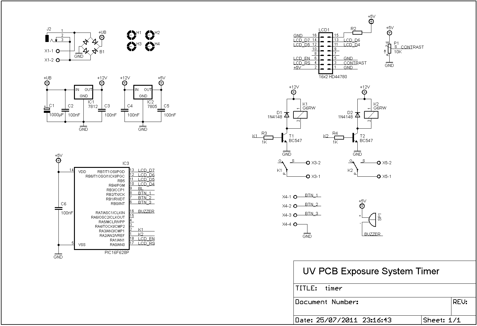
I made a new timer to switch the light panels. This new timer remembers the last exposure time, so you don’t have to remember it yourself anymore..
Please accept YouTube cookies to play this video. By accepting you will be accessing content from YouTube, a service provided by an external third party.
We use cookies to ensure that we give you the best experience on our website. If you continue to use this site we will assume that you are happy with it.