I updated this old exposure box by fitting it with my new timer.


Connection circuit:
Available Products:
Oct 24 2011
I updated this old exposure box by fitting it with my new timer.
Connection circuit:
Available Products:
Aug 28 2017
When I etch my own circuit boards, sometimes it happens that there is a very small short on the board. This short is difficult to find. To burn this short away it is handy to have a power supply that can deliver lot of current. My heaviest lab supply however can only supply 6A. Therefore I made this project:
This project is a 5V power supply with an adjustable current limit up to 30A. This power can not be outputted continuously. To make the 5V I used an old ATX PC power supply, these can supply a lot of current on the 5V line.


I have put 12 high power transistors on the secondary side of the power supply to regulate the voltage/current. The transistors are mounted to actively cooled heat sinks. 2 extra power transistors are added to drive the other transistors.

The heat sinks are from 2 old Pentium 2 processors. On top I put a few fans.

I found a few LCD voltmeters in my junk supply. These I have used in this project as volt and ampere meter.
Test layout:

Mounted:

With the switch the output can be enabled. The switch has 3 positions:
-Neutral position = OFF
-Spring return position = output on as long as the switch is activated
-Latch position = output permanent on
The 2 panel meters need their own power supply (isolated voltage), this I solved by adding a small transformer followed by 2 7805 regulators.

This part is the drive circuit of the transistors. This also include the current measurement:
Circuit:

The big pile of resistors are used because the power in the resistors at these currents is very high. I could have used a lower resistance value, but I did not have that in stock. From these resistors I had a partial reel (SMD).


PCB build in:


Ready:


Oct 03 2017
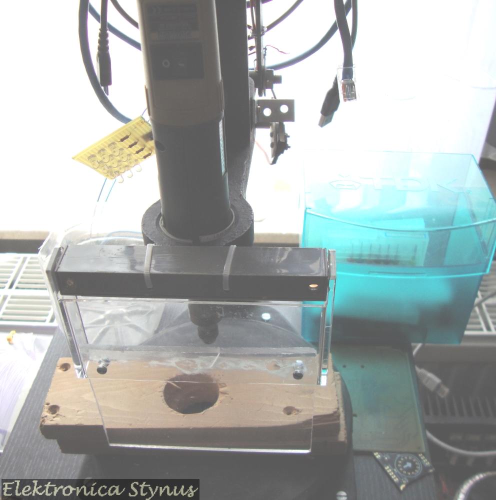
In the pictures in the previous update a cd case is used as a safety glass in front of the drill. This is rather thin, therefore I decided to exchange it to 4mm plexiglas. This new plexiglas is hinged by the cover of an old tape deck.
Old situation:

New situation:
Apr 27 2018
Some time ago I bought a lot of Weller soldering irons at an auction for cheap. Between these where a few DSX 80 de-soldering irons.

I also had an old Weller IG101 solder station (bought earlyer from another hobbyist), unfortunately I had no iron for this one and the DSX 80 could not be connected to this one. Time to convert the IG101 to newer standards.
IG101 station:

To use this station a few alterations where required. Most important is that it is 24V input, I want to change this to 230V. Also I did not like the connection for the vacuum to be on the side of the unit, so I moved it to the front (same as the modern units). The vacuum is created by a venturi valve, the air output of this valve is still on the side, since the enclosure was too small for another bend.
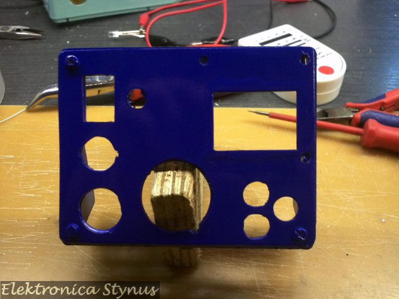
First I closed the old holes for the air connections and added a cut-out for a 230V power connector. The cover will later be painted making these “fixes” invisible.

I placed the valve on the bottom of the enclosure. On top of the valve a metal plate to mount the toroid transformer (2x12V 100VA)
Next the front panel was changed to incorporate the vacuum connection, Nokia 5110 LCD and buttons.
The old electronics where replaced with a new board driven by a PIC microcontroller.
Old:
New:


Circuit diagram:

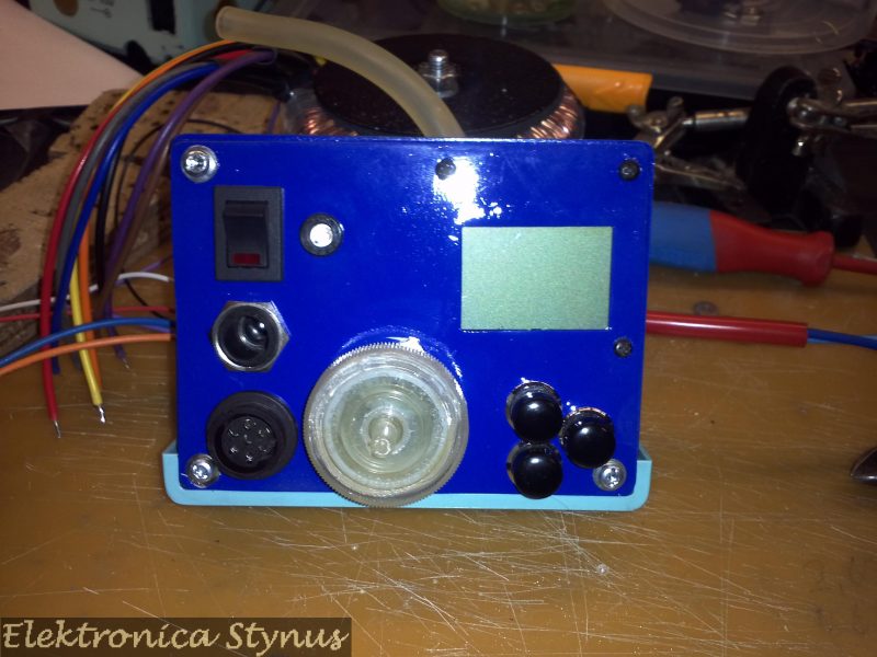
The finished result:


Mounted next to a standard solder station:

In use:
Firmware: Link
Apr 10 2023
Some time ago I bought a lot of Weller soldering irons at an auction for cheap. For the de-soldering iron I already made a station. In this lot were also a WMRT soldering tweezers cable. Next to that I bought a WMRP iron at a ham flea market. Only problem was that I do not have a station for these. I could buy one, but they are rather expensive.


After some searching for options I came across this site: http://kair.us/projects/weller/index.html I immediately ordered myself a set of boards to make a DIY one.

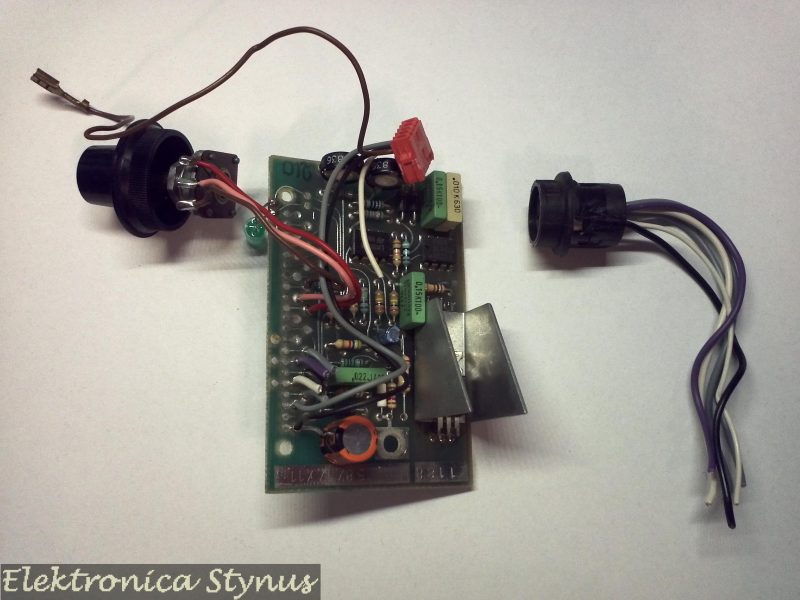
However I then came to the conclusion that I did not really like having 2 extra boxes on my desk for the stations. I want something that is small and hides somewhere. Maybe underneath the soldering iron stand. So I designed my own board and enclosure to 3d print. A few weeks later the boards came in.

The display and rotary encoder are now on a separate board that mounts at a right angle to the main board. On the back end of the board panel is also a board to mount in the WMRT holder because I suspected it was broken. (Later on I found out it was still ok.)
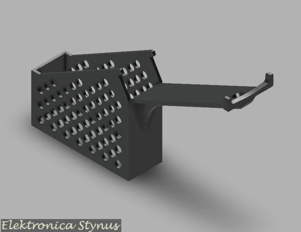
3D Design:


For both the WMRT and WMRP this part was exactly the same.
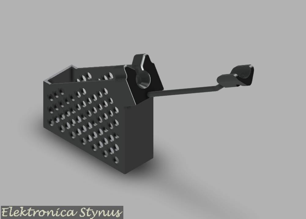
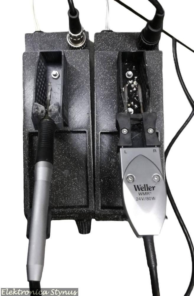
Next part was a holder for the iron. I could either build something out of metal or 3d print it. I chose for the second. The base was printed out of normal PLA since it does not really get hot unless a piece of molten solder falls on it. For the holder it is a different story. I needed a material that can handle high temperatures. This was not easy to find, but I found out that objects made in the resin printer can handle the heat quite well if you do not force the tips into it. Therefore I chose to print these out of resin.
For the WMRT the complete thing is resin with a magnet pushed in. For the WMRP the main part is resin, but the long thin support I made from 6mm² copper wire.
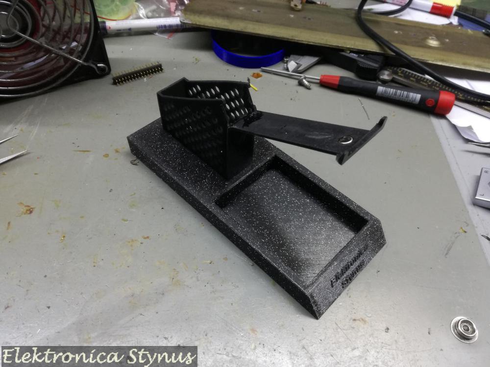

On the bottom of the iron bases I glued some washers. In the station part are some magnets, this makes that the base does not move easy on the station part, but can be detached when needed.
Next I needed a way to connect them to the 12V desk PSU. I also wanted a way to switch them on / off. So another box with switches needed to be build.


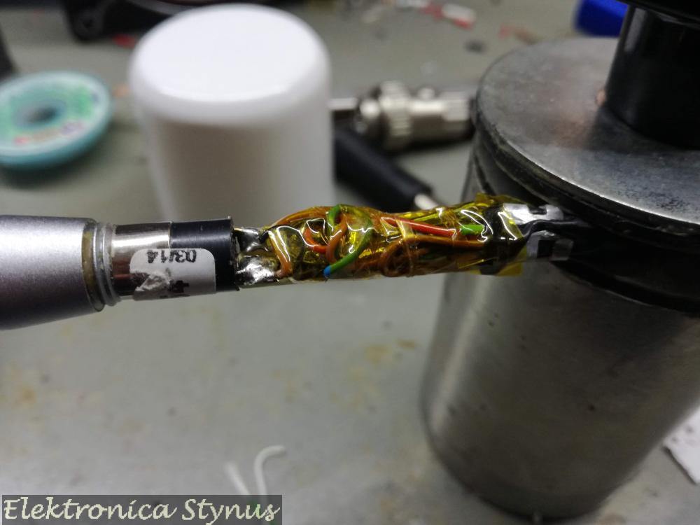
Ok, so now the WMRT works, but the WMRP I found out was not a WMRP but a WXMP. This means that the reed switch is replaced by a hall sensor and a lot of electronics are added. I removed this board and replaced it by a piece of experiment board with a reed switch from a door contact and the KTY 82 temperature compensation.

Now my desk looked like this:

As you can see the front of the stations is still open, so this was the next project. For this I used some black mirror transparent plexi. The button was 3D printed.
Off:

On:

Files / Links:
Oct 02 2023
For some time I wanted an camera to inspect solder joints / SMD parts.
What I wanted it to have was:
I found a few options, but they ware either too expensive, or the quality too low. Some time went by and then I came across a camera module at a HAM flea market. This one was not too expensive, but was only a camera module that was open on all sides. Therefore the first job was to design an enclosure. I was inspired by a professional version:


The enclosure I 3D printed in PLA. For the rails I used some old printer guide rails with slide bearings on them.


The left picture is when the camera is not in use. It is pushed completely to the back and the slides are locked in place with a magnet. The other 2 pictures are when it is slide out and in use.
Inside the enclosure it looks like this:


It contains a PCB that receives bus signals, drives the LED ring and forwards messages that are meant for the camera. For the connection of the camera to the PC, it contains a 4ch composite to USB converter (I had this one and did not want to order an extra 1ch version).
The cable that exits the camera enclosure connects to a controller.


With this controller box I can set the zoom level, focus level, intensity of the LEDs and the iris.
In the back panel is a USB plug, this one is connected to the composite to USB converter in the camera. The other input is a 12V power adapter and a programming plug for if I need to make a firmware update.
For the cable between this camera enclosure and the controller used a USB3 cable with the ends cut off. This way I have the 4 usb2 wires and an extra 4 wires for signals and power.
Underneath the camera I made a LED rind to illuminate the area. Under that I made a polarising filter.


With this filter I can change the polarisation angle of the LED ring with respect to the angle of the filter on the camera lens by rotating the polarisation ring. This makes it possible to make text on IC’s visible that would normally be hard to see. For example, below is one picture with the filter at a random angle and then rotated to a good visibility:


More details on the PCB’s:
The LED ring / camera controller board:


Controller Board / 28pin PIC breakout board:


Mar 17 2024
For a TCPS soldering iron that was in a auction some time ago I wanted to make a power supply. In my parts collection I had a spare Weller transformer that was perfect for this. For the enclosure I used an enclosure of a 230->110V transformer that I also got very cheap at an auction some time ago. The front panel is 3D printed. To store the soldering iron and the tips I also 3D printed a drawer that is mounted underneath the power supply.


