Most commented posts
- Resistor Decade Box — 15 comments
- Desoldering Station — 12 comments
- 3D Printer UV Curing Device — 6 comments
- ESR-Meter – Update — 4 comments
- Dust extraction – Part 4: Solid State Relay — 4 comments
Feb 07 2008
Today I got a lot of the bugs out of the software (I hope ![]() ). Tomorrow I’m going to test the circuit with the led’s connected.
). Tomorrow I’m going to test the circuit with the led’s connected.
Video:
Please accept YouTube cookies to play this video. By accepting you will be accessing content from YouTube, a service provided by an external third party.
If you accept this notice, your choice will be saved and the page will refresh.
Feb 08 2008
On a sale I found a counter, and thought it would be nice to have that on my drill press to count the holes I drill. so I bought it and mounted it.
Pictures:
The counter: (Mounted with double sided tape)

The switch (Normally closed contact):


Circuit:

Feb 19 2008
In school we got the assignment to make a robot car for a project week. Therefore I decided to use this car for that project. The project week is after the Easter vacation. The hardware must be finished then, the software will be written in that week.
Today I made a IR approximation sensor. The sensors I wanted to use before turned out to be a bit disappointing after some tests. I could not get the range to extend 5mm. For the new version I have used some louse IR leds and TSOP1738 ir receivers. I have a test version on breadboard.
Circuit: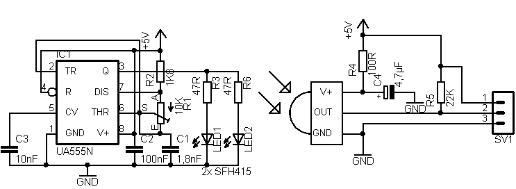
Video:
The green led on the bottom is the output.
I don’t know for sure witch pic I’m going to use, but I think it’s going to be a 16F627. To control the motors I’m going to use a L293 H-bridge IC.
Mar 02 2008
Mar 09 2008
Today I etched and partially assembled a sensor pcb (I don’t have all the components yet)


Mar 17 2008
Our workgroup is going to build 2 robot cars, 1 off them is already described, the other one is a tank.
Pictures:


Mar 22 2008
Today I etched and assembled the main pcb for my robot car. Then I mounted it and wired it all up.
Pictures:


Mar 23 2008
Mar 23 2008
I got some cheap RGB led bars from Ledsee. Therefore I decided to make a moodlight where on I was already working with those led bars. I’m going to make an housing of aluminium U profile’s with a plexi cover. And with on the ends XLC connectors to connect multiple moodlights with each other. In each profile there will be 1 led bar and 1 controller. The controller can be set as master or as slave. The communication is serial protocol but on 0-5V level.
Pictures of the led bars:


The led bar in working (dimmed):

(Picture from http://vdbeke.gnimsch.net/lichtorgel.htm)
A drawing of how I plan it to make:

The green is the controller and the raised grey part is the led bar.
For the controller I’m going to use an SMD PIC16F628 with an ULN2003 for driving the led’s.
Circuit drawing:

Circuit board: 


