Most commented posts
- Resistor Decade Box — 15 comments
- Desoldering Station — 12 comments
- 3D Printer UV Curing Device — 6 comments
- ESR-Meter – Update — 4 comments
- Dust extraction – Part 4: Solid State Relay — 4 comments
Apr 20 2011
When I fitted my desk with led lighting I had to remove my solder fume extractor. Therefore I build a new one now.
The new one is build from pvc pipe (which is build from pvc L-profiles). The fumes are sucked away and brought to a filter. (The old extractor only sucked the fumes away so they didn’t come in my face).
I have put 5 50mm fans right in front of the solder place:

Video of the test:

The smoke is transferred trough the pipe to 2 120mm fans, on these fans I’m going to mount an filter, but I don’t have that yet.


Apr 25 2011
I rather play games on my pc then on my playstations, but I think the controllers for the ps2 are handy. Therefore I wanted to use them on my pc.
After some searching I came across this on eBay:


This converter costs about 1,5€ (including shipping), so I couldn’t even build it for this kind of money.
So I ordered one and 2 weeks later I received it .I thought the plastic was a bit fragile, and it didn’t take long to break around the screws. Therefore I decided to make a enclosure around it. I also replaced the usb cable with an usb b connector. The enclosure is a recycled one, that explains why there are some holes in the back.


May 01 2011
I received an email from Chris Gammell, that I won a prize in the 555 Contest. It is one of the door prizes :).
What I won: $20 to SparkFun and 40 555 Timers from HackHut
Thanks HackHut and SparkFun!!!
May 22 2011
Today there was a Radio flea market in Eksel.
What I bought (for 37€ including entrance fee):

Pictures:


May 28 2011
I was using my network more intensely to transfer files the last weeks. And I got tired of waiting, so it was time to update my network. So I ordered a new switch and router from de-computershop.be, and today they arrived :).
My old “fast ethernet” 100Mbit/s equipment:

Linsys WR454GL 4 port router
D-Link DES-1005D 5 port switch
![]()
My new “Gigabit” 1000Mbit/s equipment:

Linsys E2000 4 port router

Cisco SD2005-G2 5 port switch

The new gear is working great, the only downside is that you need to install a config program on the pc to config the router. It has a build in web interface, but it doesn’t cover all the settings :s.
Jun 22 2011
The stirring mechanism from my old etching tank was broken again. Therefore I decided to make a new etching tank. This time a spray etching tank.
I started with making a double bottom on an square bucket. I drilled some holes in that bottom. Two of the holes are for guiding the pump tubes. The rest is to allow the etchant to drain back down.


I used some pneumatic tube for the pump. I heated it to give it a spiral shape. Then I turned it into a tube. I’m going to drill some holes in the side of the tube, for the etchant to come out. The tube is coupled to the motor with a piece of coax insulation.


I have tried a few ways to mount the motors.
First a used some threaded rods.


I used some plastic spacers to mount the rods. This way the etching fluid can’t come in contact with it.
But after some testing this way turned out to be not
At a second attempt I used some aluminum to make it stronger.

Then I came across of a big bar of pvc while cleaning up. This was the result after drilling a few holes:


This is as sturdy as the aluminium, but doesn’t dissolve in the etchant.
I did a dry test with it:
Jul 16 2011
One of the Batteries from my Bosch cordless drill machine had died. I could buy a new one but that is rather expensive. So I opted to take the batteries out and put a cable on it. The cable plugs into my 12V power supply that powers my lights etc.
The cells inside (5 cells at 0V):

I have mounted a cable gland in the plastic enclosure from the old battery so I have a strain releave for the cable.

Plugged in the drill:

I added a diode to the power supply to protect my power supply against voltage spikes from the motor.

The downside of this is of course that I have a cable connected to it now. But I still have 1 battery that functions so I can still work wireless :p. But if I’m working at the workbench and the battery is flat, then I can use the cable to avoid waiting for the charger. Another downside is that my LED lights dim as I start the drill, this is because it draws too much current. The power of the drill isn’t as big as on the battery. My power supply delivers 12V while the battery does 14.4V.
Jul 26 2011
If I had to expose a double sided PCB with my previous exposure box, I needed to turn it on twice. (1 time for the top, and 1 time for the bottom) To solve this problem it was time to build a new version. This new version will do the 2 side’s at once.
This time I chose for LED’s instead of fluorescent light, so I designed some PCB’s to mount the leds on to. The PCB’s will be connected per 6. This allows me to exposure PCB’s off 20 * 30cm max. The top of the board has no solder mask. This works as a reflector.

Soldered:

Test:

Then came the biggest work: The case make. To save space I didn’t use the traditional flap open model but a kind of sliding model. Where the glass panels slide out.

You can pull the upper plate up to insert the pcb between the glass sheets and to clamp it.
The base plate with spacers and two side plates::

With the slider mounted:


Test with glass in it:

I added some springs on the screws to make the hinges clamp the glass

On the front I added some bulletsnaplocks.

The top plate mounted with the buttons / LCD on the place where they should be mounted.

For the power supply I used a 20V toroidal transformers. The voltage is a bit high, so I used some switching voltage regulators to power the led pcb’s.
 |
 |

(One of the voltage regulators is still on order.)
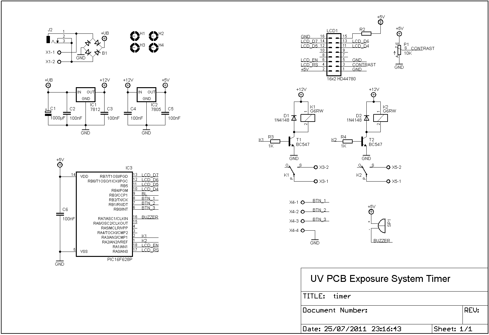
I made a new timer to switch the light panels. This new timer remembers the last exposure time, so you don’t have to remember it yourself anymore..
Please accept YouTube cookies to play this video. By accepting you will be accessing content from YouTube, a service provided by an external third party.
If you accept this notice, your choice will be saved and the page will refresh.
 |
 |

Build in the case:

Aug 16 2011
The project is finished now.
Some pictures from during the build:
Spray painted the sides + bended a top cover plate.


Mounted the front plate:

Inside:

Finished:


Placed on the location of the old exposure box:


With the slide out:

Open:

Clamped PCB:

Files
PCB files LED panels: Download
PCB files timer: Download
PCB files power supply: Download
Available Products:
Sep 04 2011
Some time ago the motor from the drill had died. So I replaced it with the Proxxon that I bought for my cnc machine.

A few weeks later the leds underneath died. I had some 3W leds + drivers in stock, so I decided to build a led driver and put a 3W led under the PCB.
Led driver:

Circuit drawing & PCB:
 |
 |
(External variable resistor = 100K)
Fixed to the board:

Led:

Test:


Files
PDF files LED driver pcb: Download


