Category: Power Supplies

Mini Lab Power Supply

Some time ago I saw Turbokeu’s his mini power supply, and I thought “I can build a smaller one”. A month later I got an enclosure from a 12Vdc => 230Vac inverter (Thanks Jeroen!). This case was perfect for my mini psu. The volume off Turbokeu his supply is 1323cm³and mine will be 588cm³.

The circuit I used is based on an article Elektor published in march 98 (Called “Regelbare voeding” in Dutch). The displays are DPM125 witch I bought at an electronics flea market. The power supply delivers 3-24V at 1A. But this is only for short times because the case is used as heat sink.
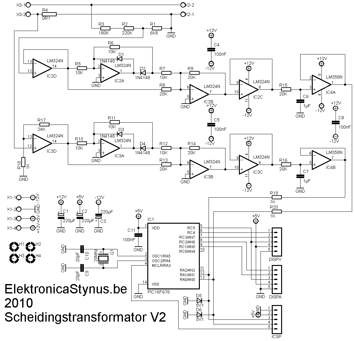
Circuit mainboard:

schema Mini Lab Voeding

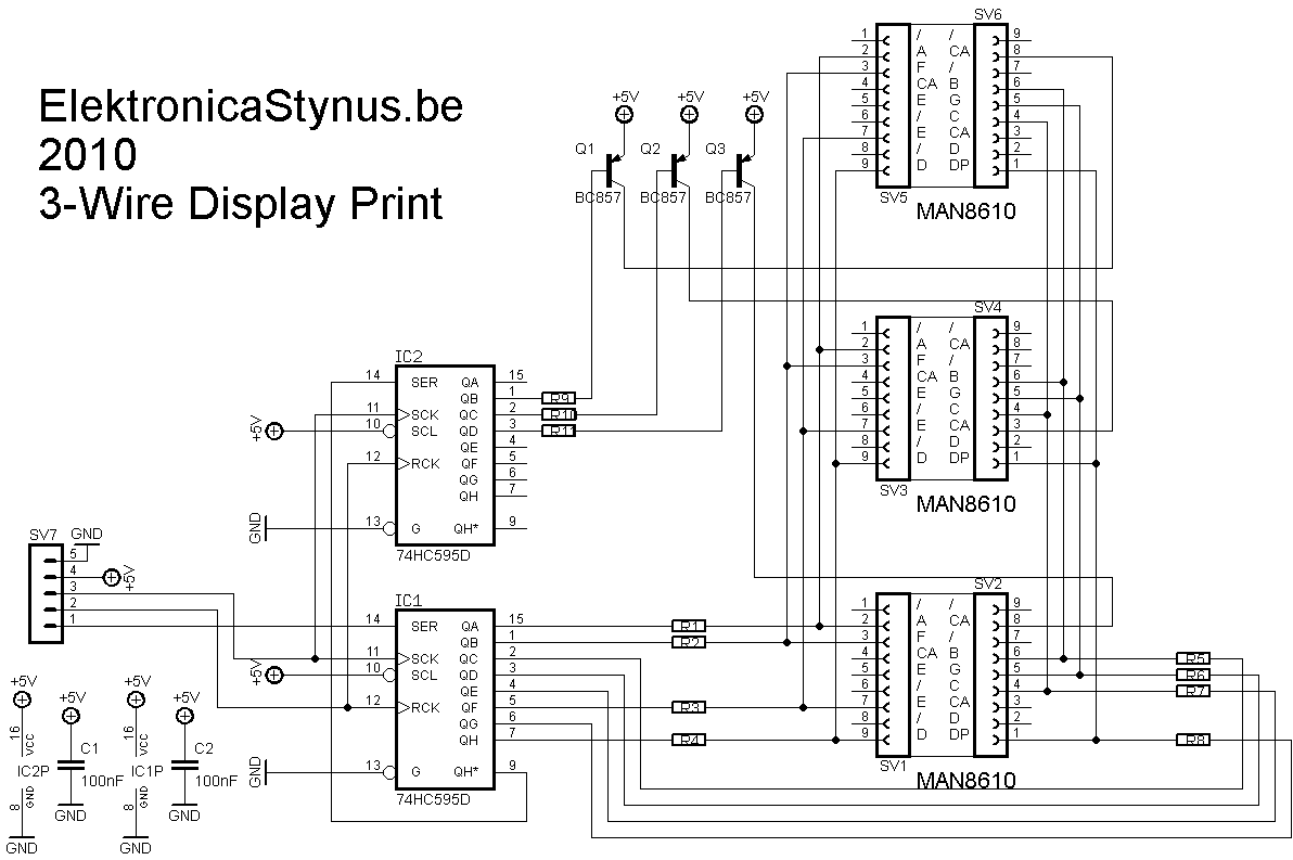
Circuit display supply:

schema Mini Lab Voeding

Pcb mainboard:

print Mini Lab Voeding

Pcb display supply:

print Mini Lab Voeding

Part list (only from the mainboard):

R1 1K 1206
R2, R3 47K 0805
R4, R6 270K 0805
R5 3K9 0805
R7 15K 0805
R8, R9, R14 4K7 0805
R10, R11 220R 0805
R12, R13 1R 1W
R15 3K3 1W
C1 4700µF
C2, C4, C5, C6, C7 100nF 0805
C3 100µF
D1, D2, D3, D4, D6, D9 1N4007 SMD DO214BA
D5, D7 BAT85
D8 5V6 zener
IC1, IC2 TLC271
IC3 78L09
POT1, POT2 1K
Q1, Q2 IRF540
TR1 transformer

Pictures:

Mini Lab Voeding

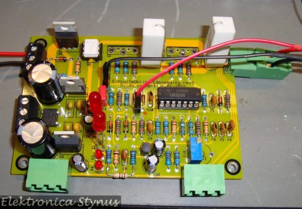
The top side of the mainboard:

print Mini Lab Voeding

Bottom side:

print Mini Lab Voeding

Bottom side of the display supply:

print Mini Lab Voeding

Top side:

print Mini Lab Voeding

Here you can see how much space is left:p:

Mini Lab Voeding

Mini Lab Voeding

Closed:

Mini Lab Voeding

Mini Lab Voeding

2 pictures with my hand as size reference.

Mini Lab Voeding

Mini Lab Voeding

Breadboard Power Supply

After my 7805 of my previous breadboard power supply was broken because of a to small heat sink, I decided to build a new version. This new version also delivers 12V. Both voltages can deliver 0.5A.

The case is from a cheap pc power supply.

Circuit:

Schema

Pictures:

Breadboard Power-Supply

Breadboard Power-Supply

Breadboard Power-Supply

Safety transformer V2

I had a external light bulb in series with my previous safety transformer to limit the output/short circuit current. This gave the problem that sometimes a bulb would fall on the ground with changing it. So I decided to make a new version with the light bulbs inside. The previous version had a 140VA transformer and sometimes that was not enough. So I build a new one with a 300VA transformer.

Measuring PCB:

This time I wanted to put a voltage and current meter in it. I could just buy them, but where is the fun in that? So I made them myself. The voltage is lowered by a voltage divider, then rectified with a opamp precision rectifier. Then it is levelled by a RC filter which sends it in a AD converter. The current is measured with a 0,1 Ohm series resistor. Because off the current there is a voltage drop across the resistor that is proportional to the current. That voltage is amplified an rectified and let to the ad converter in the pic.

Scheidingstransformator V2 Schema Scheidingstransformator V2 print

Meetprint

Display

The pic has to drive 6 7-segment displays. To save IO pins to do this I have decided to make a circuit with 2x 74HC595 ic’s. Now it takes only 3 pins per display, so 6 pins in total. 1 of the 2 74HC595 ic’s selects witch 7 segment display is on, the other one drives the digits.

Scheidingstransformator V2 Schema Scheidingstransformator V2 print

Displayprint

Displayprint


Light bulb indicators

To indicate witch lights are burning I made 3 holes in the front and let some optic fiber from there to the light bulbs.


Power supply

To power these 3 pcb’s I made a separate power supply pcb. It delivers +12V, -12V and +5V.

I used a transformer I had lying around, this transformer outputted 2*24V. This has the disadvantage that the 5V regulator gets very hot if I use a linear one. So I decided to use a switching one.

Scheidingstransformator V2 Schema Scheidingstransformator V2 print

Voeding

Main circuit

As you can read above, the current is limited by setting a light bulbs in series with the load. I have put 3 light bulbs in it, via 3 switches the bulbs can be selected. A forth switch can bypass the bulbs. To limit the output current then and switch the output on/off I used a 2A circuit breaker.

If you put 2 transformers “back to back” then you lose some voltage at the output. Therefore I’ve put a 60VA transformer that can put 15V on or of the output.

For the output I used 2 safety plugs and a wall socket.

Kast schema

Picture:

Overzicht foto

The front panel:

Frontje

If I receive my PIC16F676 then I can start programming

Safety transformer V3

I came across an ad form Stefan Haesen, he had a bunch of transformers and motors for sale at a low prize. I reacted and a few days later the trunk of my car was full. Thanks Stefan!

Between the transformers there as a 1000VA safety transformer and a 1500VA variac. I decided to build a variable safety transformer with these. For the case I used an old pc case in which I made a chassis. I also have put some wheels underneath it. The measuring print will be the same as in V2.

Because this transformer is big I had to build something to limit the inrush current.

Pictures:

PC case with reinforced bottom and wheels:

Scheidingstransformator V3

Variac:

Scheidingstransformator V3

Front panel almost finished

Scheidingstransformator V3


Inrush current limiter

inschakelvertraging schema

Scheidingstransformator V3

The power supply:

Voeding

I build all the pcb’s in the case of a pc power supply. This way it is easy to mount in the big case.

aansturing

compleet

compleet

I’m still going to finish my safety transformer V2 because that version has a current limit and this version doesn’t. I have taken V1 apart for the parts.

Lab Power Supply 0-30V 0-6A

I’m building another power supply. The specs of the power supply will be 0-24V at 6A, but they can be easily adjusted to your own needs.

Pictures of the parts that are ready:

The back side and heat sink:


The volt and ampere meter:


The help power supply:

Safety transformer V2 – Update

After finishing the dummyload project, I remembered that this project uses the same display pcb’s. Therefore I could reuse most of the code. So I finished this project as well. The pic in the project is now a PIC16F1825 which operates at 32Mhz.

http://image.elektronicastynus.be/58/1367676911.jpg

http://image.elektronicastynus.be/58/1367676912.jpg

The code:

'****************************************************************
'*  Name    : Scheidingstransformator V2                        *
'*  Author  : Stijn Coenen ElektronicaStynus.be                 *
'*  Notice  : Copyright (c) 2013 Stijn Coenen (Stynus)          *
'*          : All Rights Reserved                               *
'*  Date    : 01/05/2013                                        *
'*  Version : 1.3                                               *
'*  Notes   : This code is provided to you as is, without       *
'*          : warranty of any kind.Use at own risk!!            *
'**************************************************************** 
Device = 16F1825
Config1 FOSC_INTOSC, WDTE_OFF, PWRTE_ON, MCLRE_OFF, CP_OFF, CPD_OFF, BOREN_OFF, CLKOUTEN_OFF, IESO_ON, FCMEN_ON
Config2 WRT_OFF, PLLEN_ON, STVREN_OFF, BORV_19, LVP_OFF
Xtal = 8
'****************************************************************    
'EN: Declarations
'NL: Declaraties
    'Displays
        Symbol  Disp_klok       = LATC.5
        Symbol  Spanning_Data   = LATC.4
        Symbol  Spanning_Latch  = LATC.3
        Symbol  Stroom_Data     = LATC.2
        Symbol  Stroom_Latch    = LATC.1
        
    'EN: Measurement values
    'NL: Meetwaardes
        Dim     Spanning        As Word
        Dim     Stroom          As Word      
                  
        Symbol  N_Samp_U        = 15          
        Dim     GemU[N_Samp_U]  As Word          
        Symbol  N_Samp_I        = 15         
        Dim     GemI[N_Samp_I]  As Word
        
    'EN: Display values
    'NL: Display waardes  
        Dim     DispSpanning    As Byte
        Dim     DispStroom      As Byte
    
        Dim     DispArU[3]      As Byte 
        Dim     DispArI[3]      As Byte              
        
        Dim     IntCase         As Byte
        Dim     IntX            As Byte
        Dim     IntDisp         As Byte       
        
        Dim     X               As Byte
        Dim     Temp            As Byte
        
    'EN: Settings AD converter
    'NL: Instellingen AD converter 
        Declare Adin_Res        10 
        Declare Adin_Tad        FRC  
        Declare Adin_Stime      250         
        
    'EN: Connections 7 segment displays on the 74HC595 pcb's
    'NL: Aansluitingen 7 segment displays aan de 74HC595 op de printjes    
                            'dPecgbfa
        Symbol  Nul       = %01001000      '       a        '0         
        Symbol  Een       = %11101011      '     #####      '1
        Symbol  Twee      = %01010010      '     #   #      '2
        Symbol  Drie      = %01100010      '   f # g # b    '3
        Symbol  Vier      = %11100001      '     #####      '4
        Symbol  Vijf      = %01100100      '     #   #      '5
        Symbol  Zes       = %01000100      '   e # d # c    '6
        Symbol  Zeven     = %11101010      '     #####      '7
        Symbol  Acht      = %01000000                       '8
        Symbol  Negen     = %01100000                       '9
        Symbol  Uit       = %11111111                       'Out
        Symbol  Streep    = %11110111                       'Bar
    'EN: Connections of the transistors On the 74HC595 pcb's
    'NL: Aansluitingen Transistoren aan de 74HC595 op de printjes
        Symbol  disp1     = %00001100  
        Symbol  disp2     = %00001010  
        Symbol  disp3     = %00000110             
       
    'EN: Misc
    'NL: Diverse
        Symbol  TMR0IF    = INTCON.2
        
        'Tris registers 
        TRISA             = %11111111
        TRISC             = %00000000
         
        All_Digital       = true        
    
        On_Hardware_Interrupt GoTo Interrupts
'****************************************************************    
Opstarten:     
    'EN: Set clock to 64 Mhz
    'NL: klok instellen op 64 Mhz
    OSCCON  = %11110010

    Clear 'ram

    'EN: Timer0 setup to drive the displays
    'NL: Timer0 instellen om de displays aan te sturen
    OPTION_REG  = %00000111
    
    INTCON      = %10100000
    
    'EN: Settings AD converter
    'NL: Instellingen AD converter     
    ADCON1  = %10110000
    
GoTo Main         
'****************************************************************   
Interrupts:
    Context Save
    If TMR0IF = 1 Then
        TMR0IF = 0      'Reset flag
        TMR0   = 230'   'Preloard timer

        'EN: Loading data for the display that is driven this interrupt
        'NL: Data inladen voor het display dat deze interrupt wordt aangestuurd
        DispSpanning    = DispArU[IntCase]
        DispStroom      = DispArI[IntCase]
        
        'EN: Get the transistor settings and set the decimal point
        'NL: Transistoren info uitlezen en de comma aanzetten
        Select IntCase 
            Case 0
                IntDisp = disp1       
            Case 1          
                IntDisp = disp2 
            Case 2          
                IntDisp = disp3         
                DispStroom.6    = 0 
            Case Else
                IntDisp = 255
                IntCase = 0                
        EndSelect
                           
        'EN: Outputting transistors data 
        'NL: Transistor data inklokken
        For IntX  = 0 To 7
            Spanning_Data   = IntDisp.7
            Stroom_Data     = IntDisp.7
            Disp_klok       = 1           
            IntDisp         = IntDisp * 2             
            Disp_klok       = 0
        Next    
        'EN: Outputting display data 
        'NL: Display data inklokken
        For IntX  = 0 To 7
            Spanning_Data   = DispSpanning.7
            Stroom_Data     = DispStroom.7
            Disp_klok       = 1
            DispSpanning    = DispSpanning << 1
            DispStroom      = DispStroom << 1     
            Disp_klok       = 0
        Next               
             
        'EN: Latch data to the outputs of the 74hc595 ic's
        'NL: Data naar de uitgangen van de 74hc595 ic's latchen
        Spanning_Latch  = 1
        Stroom_Latch    = 1     
        
        'EN: Set counter for next interrupt
        'NL: Teller bijtellen voor volgende interrupt
        Inc IntCase
        If IntCase > 2 Then
            IntCase = 0
        EndIf
        
        Spanning_Latch  = 0
        Stroom_Latch    = 0 
    EndIf
               
    Context Restore
Return
'****************************************************************     
Main:
    While 1 = 1        
        'EN: Voltage measurement
        'NL: Spannings meting
        For X = (N_Samp_U - 1) To 1 Step -1    
            GemU[X]     = GemU[X-1]      
        Next
        Spanning        = ADIn 0
        Spanning        = Spanning /10 
        Spanning        = Spanning - 4.95 
        GemU[0]         = Spanning * 3.25'3.03
        Spanning        = 0
        For X = 0 To (N_Samp_U - 1)    
            Spanning    = Spanning + GemU[X]
        Next 
        Spanning        = Spanning / N_Samp_U
        
        'EN: Current measurement
        'NL: Stroom meting    
        For X = (N_Samp_I - 1) To 1 Step -1    
            GemI[X]     = GemI[X-1]      
        Next
        Stroom          = ADIn 1   
        Stroom          = Stroom - 55 'Offset
        
        GemI[0]         = Stroom /4.28
        Stroom          = 0
        For X = 0 To (N_Samp_I - 1)    
            Stroom      = Stroom + GemI[X]
        Next 
        Stroom          = Stroom / N_Samp_I

        'EN: Calculate value's for on the display
        'NL: Meetwaardes naar display berekenen
        For X = 0 To 2 
            Temp = Dig Spanning, X
            DispArU[X] = LRead Cijfers + Temp       
            Temp = Dig Stroom, X 
            DispArI[X] = LRead Cijfers + Temp
        Next 
        
        'EN: Delay for slower display update
        'NL: Wachten om het display niet te snel te updaten
        DelayMS 75
    Wend
'****************************************************************   
Cijfers:-  
LData Nul, Een, Twee, Drie, Vier, Vijf, Zes, Zeven, Acht, Negen, Uit, Streep     
End

Files

Code file: Download

Hex file: Download

PCB file meter pcb: Download

Safety transformer V3 – Update

The electronics of the measuring pcb from this project is exactly the same as that from the safety transformer V2 project. Therefore I could now finish this design too.

The finished result:

http://image.elektronicastynus.be/59/1367683024.jpg

http://image.elektronicastynus.be/59/1367683020.jpg

Safety transformer V3 – Update

After a few months of using this project it turned out that the solid state relays where not as reliable as first thought. One time the power relay stayed stuck close, but the resistors where not shorted by the other relay. This caused the resistors to get too hot (they are not calculated for continuous load).

The burned pcb:

After this I decided to build a new version of this pcb. This time with mechanical relays:

Circuit diagram:

PCB:

Picture:

The firmware in the microcontroller stays the same.

Lab Power Supply 0-30V 0-6A – Update

Previous part of this project: Link

On the CircuitsOnline forum there was an action to buy power supply boards. At this action I bought 2 boards. When I was looking for an enclosure to use for this project I came across this old project and decided to use the enclosure for the new power supply.

For this design other auxiliary power supplies are needed than with the previous design. Therefore I made some new boards:

1x 2x9V AC psu to power the drive circuit and fan
2x 5V DC to power the V and A meter
1x board with big capacitors

Total overview with all boards:

After a few tests, it turned out that the heatsink became too hot. To solve this a fan was added.

This fan is controlled by temperature. This control is based on a MCP9701T sensor with a PIC16F527 micrcontroller.

The board of the fan controller:


Fan controller XC8 source code + hex download

The finished result:

70V 3A Lab Power Supply Upgrade

A few years ago I bought a second-hand Systron Donner HR 70-3AI power supply. This power supply works with a pre-regulation by “dimming” the transformer to limit the power dissipation. This works ok, but the psu has a rather big output capacitor (3300µF), which makes it unsuitable for testing circuits.

After a few months the psu broke down, and instead of fixing it I decided to upgrade it by adding a new lab power supply part. For this I used a board I got from an action on circuitsonline. The heat sinks are rather small and can not handle the 210W (70V x 3A), therefore I decided to reuse the pre-regulation and have it regulate about 10V above the output voltage. For this I designed an interface circuit.

Old power supply drive board / pre-regulation driver:

New lab power supply circuit:

Interface circuit rev 1:

Interface circuit rev 2:

Interface circuit rev 3:

Circuit diagram:


The boards mounted:

Other alterations that have been done on the power supply:

  • The power transistors have been changed to transistors of the MJ11016 type
  • An extra 2x9V AC PSU has been added
  • The output capacitor has been changed from 3300µF to 150µF
  • The potentiometers are changed to different values.

The new output cap:

Total overview:

On the outside nothing has been changed to the enclosure.