I have worked on this project again. The other 2 pcb’s are ready. Now it is time for the “hard work” (programming + testing).


Apr 29 2012
I have worked on this project again. The other 2 pcb’s are ready. Now it is time for the “hard work” (programming + testing).
Nov 12 2012
I had a lot of 10mF 6V capacitors where I didn’t had a use for. After putting them in a different place again, I decided to create a sort of spot welding machine with them. The inspiration comes from a elektor magazine where something similar is done.
The intention is that the amount of energy that is put in the capacitors is adjustable. Therefore the output power into the short-circuit will be adjustable. This is controlled by a microcontroller. I will also make a measurement on the output pins, so that sending the current to the output can be delayed after contact (to prevent sparks)
For adjusting the settings I have added a display and 3 buttons. For the display I chose an HP HDSP 2111 H5, this display is smaller than an LCD and therefore fits easily on the front panel, a disadvantage is that it can only display 8 characters.
The front panel layout I want to use:

The cap pcb:

In the enclosure:

Control pcb:

The 2 pcb’s will be mounted on top of each other:

The front pcb is not made yet.
Circuits:
The capacitor pcb:

Control pcb:


Display pcb:

May 04 2013
After finishing the dummyload project, I remembered that this project uses the same display pcb’s. Therefore I could reuse most of the code. So I finished this project as well. The pic in the project is now a PIC16F1825 which operates at 32Mhz.


The code:
'****************************************************************
'*  Name    : Scheidingstransformator V2                        *
'*  Author  : Stijn Coenen ElektronicaStynus.be                 *
'*  Notice  : Copyright (c) 2013 Stijn Coenen (Stynus)          *
'*          : All Rights Reserved                               *
'*  Date    : 01/05/2013                                        *
'*  Version : 1.3                                               *
'*  Notes   : This code is provided to you as is, without       *
'*          : warranty of any kind.Use at own risk!!            *
'****************************************************************
Device = 16F1825
Config1 FOSC_INTOSC, WDTE_OFF, PWRTE_ON, MCLRE_OFF, CP_OFF, CPD_OFF, BOREN_OFF, CLKOUTEN_OFF, IESO_ON, FCMEN_ON
Config2 WRT_OFF, PLLEN_ON, STVREN_OFF, BORV_19, LVP_OFF
Xtal = 8
'****************************************************************
'EN: Declarations
'NL: Declaraties
    'Displays
        Symbol  Disp_klok       = LATC.5
        Symbol  Spanning_Data   = LATC.4
        Symbol  Spanning_Latch  = LATC.3
        Symbol  Stroom_Data     = LATC.2
        Symbol  Stroom_Latch    = LATC.1

    'EN: Measurement values
    'NL: Meetwaardes
        Dim     Spanning        As Word
        Dim     Stroom          As Word

        Symbol  N_Samp_U        = 15
        Dim     GemU[N_Samp_U]  As Word
        Symbol  N_Samp_I        = 15
        Dim     GemI[N_Samp_I]  As Word

    'EN: Display values
    'NL: Display waardes
        Dim     DispSpanning    As Byte
        Dim     DispStroom      As Byte

        Dim     DispArU[3]      As Byte
        Dim     DispArI[3]      As Byte

        Dim     IntCase         As Byte
        Dim     IntX            As Byte
        Dim     IntDisp         As Byte

        Dim     X               As Byte
        Dim     Temp            As Byte

    'EN: Settings AD converter
    'NL: Instellingen AD converter
        Declare Adin_Res        10
        Declare Adin_Tad        FRC
        Declare Adin_Stime      250

    'EN: Connections 7 segment displays on the 74HC595 pcb's
    'NL: Aansluitingen 7 segment displays aan de 74HC595 op de printjes
                            'dPecgbfa
        Symbol  Nul       = %01001000      '       a        '0
        Symbol  Een       = %11101011      '     #####      '1
        Symbol  Twee      = %01010010      '     #   #      '2
        Symbol  Drie      = %01100010      '   f # g # b    '3
        Symbol  Vier      = %11100001      '     #####      '4
        Symbol  Vijf      = %01100100      '     #   #      '5
        Symbol  Zes       = %01000100      '   e # d # c    '6
        Symbol  Zeven     = %11101010      '     #####      '7
        Symbol  Acht      = %01000000                       '8
        Symbol  Negen     = %01100000                       '9
        Symbol  Uit       = %11111111                       'Out
        Symbol  Streep    = %11110111                       'Bar
    'EN: Connections of the transistors On the 74HC595 pcb's
    'NL: Aansluitingen Transistoren aan de 74HC595 op de printjes
        Symbol  disp1     = %00001100
        Symbol  disp2     = %00001010
        Symbol  disp3     = %00000110

    'EN: Misc
    'NL: Diverse
        Symbol  TMR0IF    = INTCON.2

        'Tris registers
        TRISA             = %11111111
        TRISC             = %00000000

        All_Digital       = true

        On_Hardware_Interrupt GoTo Interrupts
'****************************************************************
Opstarten:
    'EN: Set clock to 64 Mhz
    'NL: klok instellen op 64 Mhz
    OSCCON  = %11110010

    Clear 'ram

    'EN: Timer0 setup to drive the displays
    'NL: Timer0 instellen om de displays aan te sturen
    OPTION_REG  = %00000111

    INTCON      = %10100000

    'EN: Settings AD converter
    'NL: Instellingen AD converter
    ADCON1  = %10110000

GoTo Main
'****************************************************************
Interrupts:
    Context Save
    If TMR0IF = 1 Then
        TMR0IF = 0      'Reset flag
        TMR0   = 230'   'Preloard timer

        'EN: Loading data for the display that is driven this interrupt
        'NL: Data inladen voor het display dat deze interrupt wordt aangestuurd
        DispSpanning    = DispArU[IntCase]
        DispStroom      = DispArI[IntCase]

        'EN: Get the transistor settings and set the decimal point
        'NL: Transistoren info uitlezen en de comma aanzetten
        Select IntCase
            Case 0
                IntDisp = disp1
            Case 1
                IntDisp = disp2
            Case 2
                IntDisp = disp3
                DispStroom.6    = 0
            Case Else
                IntDisp = 255
                IntCase = 0
        EndSelect

        'EN: Outputting transistors data
        'NL: Transistor data inklokken
        For IntX  = 0 To 7
            Spanning_Data   = IntDisp.7
            Stroom_Data     = IntDisp.7
            Disp_klok       = 1
            IntDisp         = IntDisp * 2
            Disp_klok       = 0
        Next
        'EN: Outputting display data
        'NL: Display data inklokken
        For IntX  = 0 To 7
            Spanning_Data   = DispSpanning.7
            Stroom_Data     = DispStroom.7
            Disp_klok       = 1
            DispSpanning    = DispSpanning << 1
            DispStroom      = DispStroom << 1
            Disp_klok       = 0
        Next

        'EN: Latch data to the outputs of the 74hc595 ic's
        'NL: Data naar de uitgangen van de 74hc595 ic's latchen
        Spanning_Latch  = 1
        Stroom_Latch    = 1

        'EN: Set counter for next interrupt
        'NL: Teller bijtellen voor volgende interrupt
        Inc IntCase
        If IntCase > 2 Then
            IntCase = 0
        EndIf

        Spanning_Latch  = 0
        Stroom_Latch    = 0
    EndIf

    Context Restore
Return
'****************************************************************
Main:
    While 1 = 1
        'EN: Voltage measurement
        'NL: Spannings meting
        For X = (N_Samp_U - 1) To 1 Step -1
            GemU[X]     = GemU[X-1]
        Next
        Spanning        = ADIn 0
        Spanning        = Spanning /10
        Spanning        = Spanning - 4.95
        GemU[0]         = Spanning * 3.25'3.03
        Spanning        = 0
        For X = 0 To (N_Samp_U - 1)
            Spanning    = Spanning + GemU[X]
        Next
        Spanning        = Spanning / N_Samp_U

        'EN: Current measurement
        'NL: Stroom meting
        For X = (N_Samp_I - 1) To 1 Step -1
            GemI[X]     = GemI[X-1]
        Next
        Stroom          = ADIn 1
        Stroom          = Stroom - 55 'Offset

        GemI[0]         = Stroom /4.28
        Stroom          = 0
        For X = 0 To (N_Samp_I - 1)
            Stroom      = Stroom + GemI[X]
        Next
        Stroom          = Stroom / N_Samp_I

        'EN: Calculate value's for on the display
        'NL: Meetwaardes naar display berekenen
        For X = 0 To 2
            Temp = Dig Spanning, X
            DispArU[X] = LRead Cijfers + Temp
            Temp = Dig Stroom, X
            DispArI[X] = LRead Cijfers + Temp
        Next

        'EN: Delay for slower display update
        'NL: Wachten om het display niet te snel te updaten
        DelayMS 75
    Wend
'****************************************************************
Cijfers:-
LData Nul, Een, Twee, Drie, Vier, Vijf, Zes, Zeven, Acht, Negen, Uit, Streep
End
Files
Code file: Download
Hex file: Download
PCB file meter pcb: Download
May 04 2013
The electronics of the measuring pcb from this project is exactly the same as that from the safety transformer V2 project. Therefore I could now finish this design too.
The finished result:


May 04 2013
After a long time I decided to start again on this project. Quickly it became clear that there were still a few problems whit this project.
The first problem I encountered was that the transistors started to oscillate and draw to much base current when the voltage started to get to low. The oscillations turned out to be caused by the shutdown circuit I placed on the main pcb. After I removed this circuit the oscillations where gone. But there was still the problem of the too big base current in the transistors. This I solved by added 2 resistors to each step of the output stage.

R4 is added in this circuit. Also there needs to be a 150 Ohm 2W resistor placed between this pcb and the base of the 2N3055.
After these modifications it turned out that the power supply became a bit unstable. Therefore I replaced it by a 16V laptop charger. For the microcontroller and displays I added a voltage regulator pcb to create the required 5V.


The cooling fans need 12V, so I added a second voltage regulator pcb with a 7812 voltage regulator (mounted on the big heat sink).
When I was coding the current measurement I noticed another problem. The base current was also measured. To fix this I added a new pcb based on a ZXCT1086E5TA to measure the current trough the positive lead. This measurement however has the disadvantage to only work above 3V. This I “solved” by adding a few lines in the code which put — on the ampere display when the voltage gets too low.


To connect this pcb to the main pcb I had to mod the main pcb a bit:
New circuit:

To get a stable measurement, I take the mean value of a number of samples. For this code, the pic I originally designed into the the project, turned out to be too slow. Therefore I replaced it with a PIC16F25K22 (pin compatible). This pic operates at 64Mhz.
The code:
'****************************************************************
          '*  Name    : Dummyload                                         *
          '*  Author  : Stijn Coenen ElektronicaStynus.be                 *
          '*  Notice  : Copyright (c) 2013 Stijn Coenen (Stynus)          *
          '*          : All Rights Reserved                               *
          '*  Date    : 01/05/2013                                        *
          '*  Version : 1.2                                               *
          '****************************************************************
Device = 18F25K22
  Include "Config_Fuses_1_2.bas"
Xtal = 16
'****************************************************************
  'EN: Declarations
  'NL: Declaraties
  'Displays
  Symbol  Disp_klok       = LATB.7
        Symbol  Temp_Data       = LATB.2
        Symbol  Temp_Latch      = LATB.1
        Symbol  Spanning_Data   = LATB.4
        Symbol  Spanning_Latch  = LATB.3
        Symbol  Stroom_Data     = LATB.6
        Symbol  Stroom_Latch    = LATB.5

    'EN: Measurement values
      'NL: Meetwaardes
      Dim     Temperatuur     As Word
        Dim     Spanning        As Word
        Dim     Stroom          As Dword
        Dim     StroomFloat     As Float
        Dim     StroomPrecies   As Bit

        Symbol  N_Samp_T        = 10    'Number of measuring samples; Aantal meetwaardes
          Dim     GemT[N_Samp_T]  As Word 'Array that contains the samples; Array die de meetwaardes bevat
            Symbol  N_Samp_U        = 15
        Dim     GemU[N_Samp_U]  As Word
        Symbol  N_Samp_I        = 15
        Dim     GemI[N_Samp_I]  As Word

    'EN: Display values
      'NL: Display waardes
      Dim     DispTemp        As Byte
        Dim     DispSpanning    As Byte
        Dim     DispStroom      As Byte

        Dim     DispArT[3]      As Byte
        Dim     DispArU[3]      As Byte
        Dim     DispArI[3]      As Byte

        Dim     IntCase         As Byte
        Dim     IntX            As Byte
        Dim     IntDisp         As Byte

        Dim     X               As Byte
        Dim     Temp            As Byte

    'EN: Settings AD converter
      'NL: Instellingen AD converter
      Declare Adin_Res        10
        Declare Adin_Tad        FRC
        Declare Adin_Stime      250

    'EN: Connections 7 segment displays on the 74HC595 pcb's
      'NL: Aansluitingen 7 segment displays aan de 74HC595 op de printjes
      'dPecgbfa
      Symbol  Nul       = %01001000      '       a        '0
        Symbol  Een       = %11101011      '     #####      '1
          Symbol  Twee      = %01010010      '     #   #      '2
            Symbol  Drie      = %01100010      '   f # g # b    '3
              Symbol  Vier      = %11100001      '     #####      '4
                Symbol  Vijf      = %01100100      '     #   #      '5
                  Symbol  Zes       = %01000100      '   e # d # c    '6
                    Symbol  Zeven     = %11101010      '     #####      '7
                      Symbol  Acht      = %01000000                       '8
                        Symbol  Negen     = %01100000                       '9
                          Symbol  Uit       = %11111111                       'Out
                            Symbol  Streep    = %11110111                       'Bar
                              'EN: Connections of the transistors On the 74HC595 pcb's
                              'NL: Aansluitingen Transistoren aan de 74HC595 op de printjes
                              Symbol  disp1     = %00001100
        Symbol  disp2     = %00001010
        Symbol  disp3     = %00000110

    'EN: Misc
      'NL: Diverse
      Symbol  TMR0IF    = INTCON.2

        'Tris registers
          TRISA             =  %00111011
        TRISB             =  %00000000
        TRISC             =  %11111111

        All_Digital       = true

        On_Hardware_Interrupt GoTo Interrupts
'****************************************************************
  Opstarten:
    'EN: Set clock to 64 Mhz
      'NL: klok instellen op 64 Mhz
      OSCCON  = %01110111
    OSCCON2 = %11000111

    Clear 'ram

      'EN: Timer0 setup to drive the displays
      'NL: Timer0 instellen om de displays aan te sturen
      T0CON   = %11000111
    INTCON  = %10100000
    INTCON2 = %00000100
    INTCON3 = %00000000
    IPR1    = %00000000
    IPR2    = %00000000
    IPR3    = %00000000
    IPR4    = %00000000
    IPR5    = %00000000

    'EN: Settings AD converter
      'NL: Instellingen AD converter
      ADCON1  = %00000000
    ADCON2  = %10010111

GoTo Main
'****************************************************************
  Interrupts:
    Context Save
    If TMR0IF = 1 Then
        TMR0IF = 0      'Reset flag
          TMR0L  = 230'   'Preloard timer

            'EN: Loading data for the display that is driven this interrupt
            'NL: Data inladen voor het display dat deze interrupt wordt aangestuurd
            DispTemp        = DispArT[IntCase]
        DispSpanning    = DispArU[IntCase]
        DispStroom      = DispArI[IntCase]

        'EN: Get the transistor settings and set the decimal point
          'NL: Transistoren info uitlezen en de comma aanzetten
          Select IntCase
            Case 0
                IntDisp = disp1
            Case 1
                IntDisp = disp2
                DispTemp.6      = 0
                DispSpanning.6  = 0
                DispStroom.6    = StroomPrecies
            Case 2
                IntDisp = disp3
                DispStroom.6    = StroomPrecies + 1
            Case Else
                IntDisp = 255
                IntCase = 0
        EndSelect

        'EN: Outputting transistors data
          'NL: Transistor data inklokken
          For IntX  = 0 To 7
            Temp_Data       = IntDisp.7
            Spanning_Data   = IntDisp.7
            Stroom_Data     = IntDisp.7
            Disp_klok       = 1
            IntDisp         = IntDisp * 2
            Disp_klok       = 0
        Next
        'EN: Outputting display data
          'NL: Display data inklokken
          For IntX  = 0 To 7
            Temp_Data       = DispTemp.7
            Spanning_Data   = DispSpanning.7
            Stroom_Data     = DispStroom.7
            Disp_klok       = 1
            DispTemp        = DispTemp << 1
            DispSpanning    = DispSpanning << 1
            DispStroom      = DispStroom << 1
            Disp_klok       = 0
        Next

        'EN: Latch data to the outputs of the 74hc595 ic's
          'NL: Data naar de uitgangen van de 74hc595 ic's latchen
          Temp_Latch      = 1
        Spanning_Latch  = 1
        Stroom_Latch    = 1

        'EN: Set counter for next interrupt
          'NL: Teller bijtellen voor volgende interrupt
          Inc IntCase
        If IntCase > 2 Then
            IntCase = 0
        EndIf

        Temp_Latch      = 0
        Spanning_Latch  = 0
        Stroom_Latch    = 0
    EndIf

    Context Restore
Return
'****************************************************************
  Main:
    While 1 = 1

        'EN: Temperature measurement
          'NL: Temperatuur meting
          For X = (N_Samp_T - 1) To 1 Step -1
            GemT[X]     = GemT[X-1]
        Next
        Temperatuur     = ADIn 1
        Temperatuur     = Temperatuur * 5
        GemT[0]         = Temperatuur / 9
        Temperatuur     = 0
        For X = 0 To (N_Samp_T - 1)
            Temperatuur = Temperatuur + GemT[X]
        Next
        Temperatuur     = Temperatuur / N_Samp_T


        'EN: Voltage measurement
          'NL: Spannings meting
          For X = (N_Samp_U - 1) To 1 Step -1
            GemU[X]     = GemU[X-1]
        Next
        Spanning        = ADIn 0
        GemU[0]         = Spanning /  1.86
        Spanning        = 0
        For X = 0 To (N_Samp_U - 1)
            Spanning    = Spanning + GemU[X]
        Next
        Spanning        = Spanning / N_Samp_U


        'EN: Current measurement
          'NL: Stroom meting
          For X = (N_Samp_I - 1) To 1 Step -1
            GemI[X]     = GemI[X-1]
        Next
        Stroom          = ADIn 16
        'EN: Setting the decimal point place
          'NL: Plaats comma bepalen
          If Stroom > 500 Then 'X.XX
            StroomPrecies = 0
            StroomFloat = Stroom * (5/1024) * 10
        Else                 'XX.X
          StroomPrecies = 1
            StroomFloat = Stroom * (5/1024) * 100
        EndIf
        StroomFloat     = StroomFloat / 50
        StroomFloat     = StroomFloat / 0.005
        GemI[0]         = StroomFloat * 1.07
        Stroom          = 0
        For X = 0 To (N_Samp_I - 1)
            Stroom      = Stroom + GemI[X]
        Next
        Stroom          = Stroom / N_Samp_I

        'EN: Calculate value's for on the display
          'NL: Meetwaardes naar display berekenen
          For X = 0 To 2
            Temp = Dig Temperatuur, X
            DispArT[X] = LRead Cijfers + Temp
            Temp = Dig Spanning, X
            DispArU[X] = LRead Cijfers + Temp
            'EN: The ZXCT1086E5TA does Not work below 3V, so display bars when this happens
              'NL: De ZXCT1086E5TA werkt niet onder de 3V, dus als dit gebeurt streepjes weergeven
              If Spanning > 30 Then
                Temp = Dig Stroom, X
                DispArI[X] = LRead Cijfers + Temp
            Else
                DispArI[X] = Streep
            EndIf
        Next

        'EN: Delay for slower display update
          'NL: Wachten om het display niet te snel te updaten
          DelayMS 75
    Wend
'****************************************************************
  Cijfers:-
LData Nul, Een, Twee, Drie, Vier, Vijf, Zes, Zeven, Acht, Negen, Uit, Streep
End
The dummyload working:


Files
Code file: Download
Hex file: Download
Sep 26 2014
I was thinking about making a resistor decade box, but I found the rotary switches that are used in these most of the time rather expensive and a bit old fashioned. That’s why I decided to use a rotary encoder and select the resistors with a microcontroller.
Now I only had to find a way to “make” the resistance. Switching resistors with transistors or mosfets gives a high switch resistance and can’t handle AC voltages. That’s why I opted to use relays. The currents that need to be switched are rather small, therefore a small relay is sufficient. The relay board is used 2 times with different resistor values.
Relay PCB:
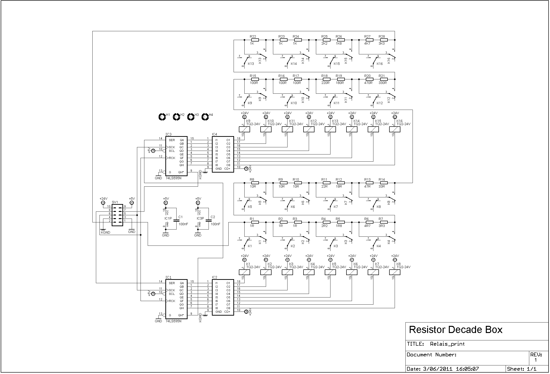


Part list:
PCB low resistance:
| 3 | 1K | R22, R23, R24 |
| 1 | 1K8 | R26 |
| 3 | 1R | R1, R2, R3 |
| 1 | 1R8 | R5 |
| 1 | 2K2 | R25 |
| 1 | 2R2 | R4 |
| 1 | 3K3 | R28 |
| 1 | 3R3 | R7 |
| 1 | 4K7 | R27 |
| 1 | 4R7 | R6 |
| 3 | 10R | R8, R9, R10 |
| 1 | 18R | R12 |
| 1 | 22R | R11 |
| 1 | 33R | R14 |
| 1 | 47R | R13 |
| 3 | 100R | R15, R16, R17 |
| 1 | 180R | R19 |
| 1 | 220R | R18 |
| 1 | 330R | R21 |
| 1 | 470R | R20 |
| 2 | 100nF | C1, C2 |
| 2 | 74HCT595 | IC1, IC3 |
| 2 | ULN2803 | IC2, IC4 |
| 16 | TQ2-24V | K1, K2, K3, K4, K5, K6, K7, K8, K9, K10, K11, K12, K13, K14, K15, K16 |
PCB high resistance:
| 3 | 10K | R1, R2, R3 |
| 1 | 18K | R5 |
| 1 | 22K | R4 |
| 1 | 33K | R7 |
| 1 | 47K | R6 |
| 3 | 100K | R8, R9, R10 |
| 1 | 180K | R12 |
| 1 | 220K | R11 |
| 1 | 330K | R14 |
| 1 | 470K | R13 |
| 3 | 1M | R15, R16, R17 |
| 1 | 1M8 | R19 |
| 1 | 2M2 | R18 |
| 1 | 3M3 | R21 |
| 1 | 4M7 | R20 |
| 2 | 100nF | C1, C2 |
| 2 | 74HCT595 | IC1, IC3 |
| 2 | ULN2803 | IC2, IC4 |
| 12 | TQ2-24V | K1, K2, K3, K4, K5, K6, K7, K8, K9, K10, K11, K12 |
Control PCB:


Part list:
| 2 | 1uF | C3, C4 |
| 1 | 10K | R2 |
| 1 | 10K | R1 |
| 1 | 16F648A (Programmed) | IC1 |
| 2 | 100nF | C1, C2 |
| 1 | Push button | S1 |
| 1 | Rotary encoder | S1 |
| 1 | REG1117-5V | IC2 |
With frontpanel:

Power supply
This part is made on experiment board, therefore there are no circuit drawings available. The pcb exists of a 18V transformer; a rectifier and a capacitor.
Everything mounted in the enclosure:

Ready:

Code in the microcontroller:
Device = 16F648A
Config FOSC_INTOSCIO, WDTE_OFF, PWRTE_ON, MCLRE_OFF, BOREN_OFF, LVP_OFF, CPD_OFF, CP_OFF

All_Digital           = true
Xtal                  = 4

Declare PortB_Pullups   On

Declare LCD_DTPin       PORTB.4
Declare LCD_ENPin       PORTB.2
Declare LCD_RSPin       PORTB.3
Declare LCD_Interface   4
Declare LCD_Lines       2

Symbol  RotEncoderA   = PORTB.1
Symbol  RotEncoderB   = PORTB.0
Symbol  RotSwitch     = PORTA.2

Symbol  PushSwitch    = PORTA.4
Dim     PushSwitchBit As Bit

TRISB                 = %00000011
TRISA                 = %01111100

OPTION_REG            = %01000000
INTCON                = %10010000
Symbol  INTF          = INTCON.1

Symbol  klok          = PORTA.0
Symbol  Data_Pin      = PORTA.7
Symbol  ZetVast       = PORTA.1

Dim  DispWaarde[7]    As Byte
Dim  SetWaarde[7]     As Byte
Dim  DispTeller       As Byte
Dim  CursorTeller     As Byte
Dim  UitHex           As Byte
Dim  UitDig           As Byte
Dim  UitCount         As Byte
Dim  ArrayTeller      As Byte
Dim  Warning          As Bit
'dim teller as byte

On_Hardware_Interrupt GoTo IrInterrupt

GoTo Init
'****************************************************************
IrInterrupt:
    Context Save
       If INTF = 1 Then
          'Flaggen resetten
          INTF = 0
          If RotEncoderA = 1 Then
             'Aftellen
             If DispWaarde[6 - DispTeller] > 0 Then
                Dec DispWaarde[6 - DispTeller]
             EndIf
          Else
             'Optellen
             If DispWaarde[6 - DispTeller] < 9 Then
                Inc DispWaarde[6 - DispTeller]
             EndIf
          EndIf
       EndIf
    Context Restore
'****************************************************************
Init:
    Cls

    UitDig = DispWaarde[3]
    UitHex = UitDig << 4
    UitDig = DispWaarde[2]
    UitHex = UitHex + UitDig
    UitHex = ~UitHex
    SHOut Data_Pin, klok, MsbFirst, [UitHex \ 8]

    UitDig = DispWaarde[1]
    UitHex = UitDig << 4
    UitDig = DispWaarde[0]
    UitHex = UitHex + UitDig
    UitHex = ~UitHex
    SHOut Data_Pin, klok, MsbFirst, [UitHex \ 8]

    UitHex = 0
    UitDig = DispWaarde[6]
    UitHex = UitHex + UitDig
    UitHex = ~UitHex
    SHOut Data_Pin, klok, MsbFirst, [UitHex \ 8]

    UitDig = DispWaarde[5]
    UitHex = UitDig << 4
    UitDig = DispWaarde[4]
    UitHex = UitHex + UitDig
    UitHex = ~UitHex
    SHOut Data_Pin, klok, MsbFirst, [UitHex \ 8]

    High ZetVast
    DelayUS 20
    Low ZetVast
                   '12345678
    Print At 1, 1, "E-Stynus"
    Print At 2, 1, "  2014  "
    DelayMS 750
    Cls

    Print At 1,1, "Set:"
    DispTeller = 0

    'Ohm teken in lcd steken
    Print $FE,$40,$00,$0E,$11,$11,$11,$0A,$1B,$00
'****************************************************************
Main:
While 1 = 1
   'Relais aansturen bij rotary encoder button druk
   If RotSwitch = 0 Then
      For ArrayTeller = 0 To 6
          SetWaarde[ArrayTeller]     = DispWaarde[ArrayTeller]
          If SetWaarde[ArrayTeller]  > 9 Then
             SetWaarde[ArrayTeller]  = 0
             DispWaarde[ArrayTeller] = 0
          EndIf
      Next

      UitDig = DispWaarde[3]
      UitHex = UitDig << 4
      UitDig = DispWaarde[2]
      UitHex = UitHex + UitDig
      UitHex = ~UitHex
      SHOut Data_Pin, klok, MsbFirst, [UitHex \ 8]

      UitDig = DispWaarde[1]
      UitHex = UitDig << 4
      UitDig = DispWaarde[0]
      UitHex = UitHex + UitDig
      UitHex = ~UitHex
      SHOut Data_Pin, klok, MsbFirst, [UitHex \ 8]

      UitHex = 0
      UitDig = DispWaarde[6]
      UitHex = UitHex + UitDig
      UitHex = ~UitHex
      SHOut Data_Pin, klok, MsbFirst, [UitHex \ 8]

      UitDig = DispWaarde[5]
      UitHex = UitDig << 4
      UitDig = DispWaarde[4]
      UitHex = UitHex + UitDig
      UitHex = ~UitHex
      SHOut Data_Pin, klok, MsbFirst, [UitHex \ 8]

      High ZetVast
      DelayUS 20
      Low ZetVast

      DelayMS 100
      While RotSwitch = 0
            DelayMS 100
      Wend

   EndIf

   'Warning teken
   Warning = 0
   For ArrayTeller = 0 To 6
       If DispWaarde[ArrayTeller] <> SetWaarde[ArrayTeller] Then
          Warning = 1
       EndIf
   Next
   If Warning = 1 Then
      Print At 1, 8, "!"
   Else
      Print At 1, 8, " "
   EndIf

   'Decade positie
   If PushSwitch = 0 And PushSwitchBit = 0 Then
      PushSwitchBit = 1
      DelayMS 100
      If DispTeller < 6 Then
         Inc DispTeller
      Else
         DispTeller = 0
      EndIf
   EndIf
   If PushSwitch = 1 Then
      PushSwitchBit = 0
   EndIf
   For ArrayTeller = 0 To 6
       If DispWaarde[ArrayTeller] > 9 Then
          DispWaarde[ArrayTeller] = 0
       EndIf
       Print At 2, 7 - ArrayTeller, Dec1 DispWaarde[ArrayTeller]
   Next
   Print At 2,8, 0
   '(Print At 1,4, Dec DispTeller
   Print $FE, $0E           'Underline cursor on
   Print $FE, $C0           'Move cursor to beginning of second line
   CursorTeller = 0
   While CursorTeller < DispTeller
       Print $FE, $14      'Move cursor right one position
       Inc CursorTeller
   Wend


   DelayMS 100

Wend
End
Hex file: link
Oct 06 2014
After a few months of using this project it turned out that the solid state relays where not as reliable as first thought. One time the power relay stayed stuck close, but the resistors where not shorted by the other relay. This caused the resistors to get too hot (they are not calculated for continuous load).
The burned pcb:


After this I decided to build a new version of this pcb. This time with mechanical relays:
Circuit diagram:

PCB:

Picture:

The firmware in the microcontroller stays the same.
Oct 19 2014
A while ago I decided to convert my AMA-16 milling machine to cnc. For this machine I bought some stepper drivers to save the time of building them myself. I have mounted these drivers together with some power supplies and relays in a control box. Unfortunately I have not made many pictures during the build process.
Pictures:


Bottom side vent openings:

There are 3 ventilation openings on top. I protected these with air filters to keep out the dust.

The stepper motors are connected to the control box via speakon connectors:


Interface board:

On/off switch


Control circuit:

Sensor, power and control inputs:

I have mounted a touch-screen to the front of the control box.

More info will follow in a future update.
Jul 28 2017
Previous part of this project: Link
On the CircuitsOnline forum there was an action to buy power supply boards. At this action I bought 2 boards. When I was looking for an enclosure to use for this project I came across this old project and decided to use the enclosure for the new power supply.
For this design other auxiliary power supplies are needed than with the previous design. Therefore I made some new boards:
1x 2x9V AC psu to power the drive circuit and fan
2x 5V DC to power the V and A meter
1x board with big capacitors
Total overview with all boards:


After a few tests, it turned out that the heatsink became too hot. To solve this a fan was added.

This fan is controlled by temperature. This control is based on a MCP9701T sensor with a PIC16F527 micrcontroller.
The board of the fan controller:

Fan controller XC8 source code + hex download
The finished result:


Aug 05 2017
A few years ago I bought a second-hand Systron Donner HR 70-3AI power supply. This power supply works with a pre-regulation by “dimming” the transformer to limit the power dissipation. This works ok, but the psu has a rather big output capacitor (3300µF), which makes it unsuitable for testing circuits.

After a few months the psu broke down, and instead of fixing it I decided to upgrade it by adding a new lab power supply part. For this I used a board I got from an action on circuitsonline. The heat sinks are rather small and can not handle the 210W (70V x 3A), therefore I decided to reuse the pre-regulation and have it regulate about 10V above the output voltage. For this I designed an interface circuit.
Old power supply drive board / pre-regulation driver:

New lab power supply circuit:
Interface circuit rev 1:

Interface circuit rev 2:

Interface circuit rev 3:

Circuit diagram:

The boards mounted:

Other alterations that have been done on the power supply:
The new output cap:

Total overview:

On the outside nothing has been changed to the enclosure.