Category: Projects

Cruiser Micromouse

I made this project a few years ago with some classmates in school.

The school bought the chassis and the pcbs of the cruiser micromouse. Our assignment was to write the code ourselves. The function of this robot is to run through a maze.


To test the cars we made a circuit. This is made so 1 side is a maze and the other side is a line for a line following robot.


Video of the cruiser in action:

Please accept YouTube cookies to play this video. By accepting you will be accessing content from YouTube, a service provided by an external third party.

YouTube privacy policy

If you accept this notice, your choice will be saved and the page will refresh.

Code (Bascom):

'*************************************************
'* Cruiser micromouse                            *
'* Stijn Coenen, Rob Thomas, Stijn van Roy       *
'* 3ELO2                                         *
'*************************************************
$regfile = "m8def.dat"
'Aangeven dat het intern kristal 
'op 8MHz is ingesteld
$crystal = 8000000
'**********************************
'In en uitgangen instellen
Config Portd.0 = Output
Config Portd.1 = Output
Config Portd.2 = Output
Config Portd.3 = Input
Config Portd.4 = Input
Config Portd.5 = Output
Config Portd.6 = Output
Config Portd.7 = Output
Config Portc.6 = Input
Config PORTB = Output
'**********************************
'In en uitgangen declareren
Led0 Alias Portd.0
Led1 Alias Portd.1
Led2 Alias Portd.2
Selectt Alias Portd.3
Modee Alias Portd.4
Sensor0 Alias Portd.5
Sensor1 Alias Portd.6
Sensor2 Alias Portd.7
Resett Alias Portc.6
Motor_en Alias PORTB.0
L_motor Alias PORTB.1
R_motor Alias PORTB.2
Led3 Alias PORTB.3
Led4 Alias PORTB.4
Led5 Alias PORTB.5
Buzzer Alias PORTB.6
'**********************************
'Byte's declareren
Dim Temp_register As Long
Dim Rechts_achter As Bit
Dim Rechts As Bit
Dim Rechts_voor As Bit
Dim Links_voor As Bit
Dim Links As Bit
Dim Links_achter As Bit
Dim I As Byte
Dim Led_bit As Bit
Dim Vanvoor As Bit
Dim Motorwaarde As Byte
Dim Muurbit As Bit
Dim Teller As Byte
'***********************************
'Analoge ingang instellen
Config Adc = Single , Prescaler = Auto
Start Adc
'***********************************
'Timer0 instellen (Voor de IR leds aan te sturen)
Config Timer0 = Timer , Prescale = 64 , Reference = External
'Prescaled kloksnelheid: 8000000 / 64 = 125 Khz
  'Waarde die in timer0 wordt gezet bij een     
  overflow
  Const Preload = 248
  '************************************
  'Interrupt's aanzetten
  Enable Interrupts
  Enable Timer0
  On Timer0 Interupt_label
  '************************************
  'Subroutines
    'Subroutines skippen bij opstarten programma
     GoTo Overint
     Interupt_label:
      'IR leds van de sensoren aansturen
      If Led_bit = 0 Then
         Sensor0 = 1
         Sensor1 = 1
         Sensor2 = 1
         Led_bit = 1
      Else
         Sensor0 = 0
         Sensor1 = 0
         Sensor2 = 0
         Led_bit = 0
      End If
      'De preload waarde terug in Timer0 zetten
      Timer0 = Preload
      'Motor PWM
      Incr Motorwaarde
      If Motorwaarde < 32 Then
         Motor_en = 1
      Else
         Motor_en = 0
         If Motorwaarde = 64 Then
            Motorwaarde = 0
         End If
      End If
   Return
   '*******************************************
   Buzzer_aanst:
      For I = 0 To 100
         Buzzer = 1
         Waitus 100
         Buzzer = 0
         Waitms 1
      Next
   Return
   '**********************************************
   'Analoge ingangen inlezen en omzetten naar bits
   Analoog_in:
      Start Adc
      Temp_register = Getadc(5)
      If Temp_register > 40 Then
         Rechts_achter = 1
         Led5 = 0
      Else
         Rechts_achter = 0
         Led5 = 1
      End If
      Temp_register = Getadc(4)
         If Temp_register > 60 Then
         Rechts = 1
         Led4 =  
      Else
         Rechts = 0
         Led4 = 1
      End If
      Temp_register = Getadc(3)
      If Temp_register > 60 Then
         Rechts_voor = 1
         Led3 = 0
      Else
         Rechts_voor = 0
         Led3 = 1
      End If
      Temp_register = Getadc(2)
      If Temp_register > 60 Then
         Links_voor = 1
         Led2 = 0
      Else
         Links_voor = 0
         Led2 = 1
      End If
      Temp_register = Getadc(1)
      If Temp_register > 40 Then
         Links = 1
         Led1 = 0
      Else
         Links = 0
         Led1 = 1
      End If
      Temp_register = Getadc(0)
      If Temp_register > 40 Then
         Links_achter = 1
         Led0 = 0
      Else
         Links_achter = 0
         Led0 = 1
      End If
   Return
'**************************************
Overint:
'Motors opzetten
L_motor = 1
R_motor = 1
Do
     GoSub Analoog_in
     If Links = 1 Then
         R_motor = 0
         L_motor = 1
         'Rechts draaien tot dat links niks 
 'meer gedetecteerd wordt
         Do
            GoSub Analoog_in
         Loop Until Links = 0
         L_motor = 1
         R_motor = 1
         Teller = 0
     ElseIf Rechts = 1 Then
         R_motor = 1
         L_motor = 0
         'Links draaien tot dat rechts niks 
 'meer gedetecteerd wordt
         Do
            GoSub Analoog_in
         Loop Until Rechts = 0
         L_motor = 1
         R_motor = 1
         Teller = 0
      ElseIf Links_voor = 1 Then
         R_motor = 0
         L_motor = 1
         Waitms 260
         'Links draaien tot dat vanvoor niks 
 'meer gedetecteerd wordt
         Do
            GoSub Analoog_in
         Loop Until Links_voor = 0
         L_motor = 1
         R_motor = 1
         Teller = 0
      End If
      'Als het programma 30 keer doorlopen is 
      'zonder dat er iets gedetecteerd is
      'dan kort naar links draaien
      Incr Teller
      If Teller = 30 Then
         Waitms 20
         R_motor = 1
         L_motor = 0
         Waitms 30
         L_motor = 1
         R_motor = 1
         Waitms 10
         Teller = 0
      End If
Loop
'******************************************
End

Files

Code: Download

HexAvoider

I made this project a few years ago with some classmates in school.

The plastic parts and the pcbs (kit) where bought by the school. Our assignment was to solder the pcb’s and write the program.

Normally the hexavoider goes forward. This happens by lifting the left side, the right side is then put forward and left back to the rear. Then the other side is lifted and the left side goes to the front. This is how it steps forwards.

The hexavoider has 2 types of sensors: the whiskers and the IR sensors. If the whiskers feel something then it goes backwards, turns to the other side as from where it detected and walks on. If the IR sensors detect something it will reverse and then turn. This is in always in the same direction because there is only 1 IR sensor.


Video of the HexAvoider in action:

Please accept YouTube cookies to play this video. By accepting you will be accessing content from YouTube, a service provided by an external third party.

YouTube privacy policy

If you accept this notice, your choice will be saved and the page will refresh.


Code (Bascom):

'*************************************************
'* HexAvoider                                    *
'* Stijn Coenen, Rob Thomas, Stijn van Roy       *
'* 3ELO2                                         *
'*************************************************
$regfile = "89C51RC.dat"

'Kristal = 11Mhz
$crystal = 11059200
'*************************************************
'In en uitgangen aanduiden
Config Servos = 3 , Servo1 = P1.5 , Servo2 = P1.6 , Servo3 = P1.7 , Reload = 100

Led1 Alias P0.0
Led2 Alias P0.1
Led3 Alias P0.2
Led4 Alias P0.3
Buzzer Alias P0.5
Switch1 Alias P0.4
Switch2 Alias P0.5
Links_antenne Alias P3.2
Recht_antenne Alias P3.3
Led_antenne Alias T0
Irled_left Alias P1.0
Irled_right Alias P1.1
Irin Alias P1.2
Led_left Alias P1.3
Led_right Alias P1.4

Dim index As Byte
'*************************************************
'Subroutines
  'Subroutines skippen bij opstarten programma
  GoTo Oversub
  '*************************************************
  'Ir leds laten knipperen
  Ir_led_sturen:
     For index = 0 To 100
      Irled_left = 1
      Irled_right = 1
      delay
      Irled_left = 0
      Irled_right = 0
      Delay
     Next
  Return
  '*************************************************
  'Als er links gedetecteerd is
  Links_detect:
     Led1 = 0
     GoSub Servo_mid
     GoSub Achteruit
     GoSub Achteruit
     Waitms 2000
     GoSub Servo_mid
     GoSub Rechts_draai
     GoSub Rechts_draai
     Led1 = 1
  Return
  '*************************************************
  'Als er rechts gedetecteerd is
  Rechts_detect:
     Led2 = 0
     GoSub Servo_mid
     GoSub Achteruit
     GoSub Achteruit
     Waitms 2000
     GoSub Servo_mid
     GoSub Links_draai
     GoSub Links_draai
     Led2 = 1
  Return
  '*************************************************
  'Alle servo's in de middenstand zetten
  Servo_mid:
     Servo1 = 12
     Servo2 = 12
     Servo3 = 12
  Return
  '*************************************************  'Achteruit lopen
  Achteruit:
     'links omhoog
     Servo2 = 16
     Waitms 350
     'links naar achter
     Servo3 = 8
     Waitms 350
     'links naar voor
     Servo1 = 8
     Waitms 350
     ' rechts omhoog
     Servo2 = 8
     Waitms 350
     'rechts naar achter
     Servo1 = 16
     Waitms 350
     'links naar voor
     Servo3 = 16
     Waitms 350
  Return
  '*************************************************
  'Naar rechts draaien
  Rechts_draai:
     'links omhoog
     Servo2 = 16
     Waitms 350
     'links naar voor
     Servo3 = 14
     Waitms 350
     'rechts naar voor
     Servo1 = 8
     Waitms 350
     'rechts omhoog
     Servo2 = 8
     Waitms 350
     'rechts naar achter
     Servo1 = 14
     Waitms 350
     'links naar achter
     Servo3 = 8
     Waitms 350
  Return
  '*************************************************
  'Naar links draaien
  Links_draai:
     'links omhoog
     Servo2 = 16
     Waitms 350
     'links naar achter
     Servo3 = 8
     Waitms 350
     'rechts naar voor
     Servo1 = 14
     Waitms 350
      'rechts omhoog
     Servo2 = 8
     Waitms 350
     'rechts naar voor
     Servo1 = 8
     Waitms 350
     'links naar voor
     Servo3 = 14
     Waitms 350
  Return
  '*************************************************
  'Sensoren checken
  Sensor_check:
      'Linkse antenne
      If Links_antenne = 0 Then
         GoSub Links_detect
      End If
      'Rechtse antenne
      If Recht_antenne = 0 Then
         GoSub Rechts_detect
      End If
      'IR-Leds
      GoSub Ir_led_sturen
      If Irin = 0 Then
         GoSub Rechts_detect
      End If
  Return
Oversub:
'*************************************************
   'Servo's in de middenstand zetten
   GoSub Servo_mid
Do
   'rechts omhoog
   Servo2 = 8
      Waitms 350
      If Links_antenne = 0 Then
         GoSub Links_detect
      End If
      If Recht_antenne = 0 Then
         GoSub Rechts_detect
      End If
      GoSub Ir_led_sturen
      If Irin = 0 Then
         GoSub Rechts_detect
      End If
   'Links naar achter
   Servo3 = 10
     Waitms 350
     If Links_antenne = 0 Then
        GoSub Links_detect
     End If
     If Recht_antenne = 0 Then
        GoSub Rechts_detect
     End If
      GoSub Ir_led_sturen
     If Irin = 0 Then
        GoSub Rechts_detect
     End If
   'Rechts voor
   Servo1 = 8
      Waitms 350
      If Links_antenne = 0 Then
         GoSub Links_detect
      End If
      If Recht_antenne = 0 Then
         GoSub Rechts_detect
      End If
      GoSub Ir_led_sturen
      If Irin = 0 Then
         GoSub Rechts_detect
      End If
   'links omhoog
   Servo2 = 16
      Waitms 350
      If Links_antenne = 0 Then
         GoSub Links_detect
      End If
      If Recht_antenne = 0 Then
         GoSub Rechts_detect
      End If
      GoSub Ir_led_sturen
      If Irin = 0 Then
         GoSub Rechts_detect
      End If
   'rechts naar achter
   Servo1 = 15
      Waitms 350
      If Links_antenne = 0 Then
         GoSub Links_detect
      End If
      If Recht_antenne = 0 Then
         GoSub Rechts_detect
      End If
      GoSub Ir_led_sturen
      If Irin = 0 Then
         GoSub Rechts_detect
      End If
   'Links Naar Voor
   Servo3 = 14
      Waitms 350
      If Links_antenne = 0 Then
         GoSub Links_detect
      End If
      If Recht_antenne = 0 Then
         GoSub Rechts_detect
      End If
      GoSub Ir_led_sturen
      If Irin = 0 Then
         GoSub Rechts_detect
      End If
Loop
'*************************************************
End

Top

Files

Code: Download

Line Follower

I made this project a few years ago with some classmates in school.

After we completed our Cruiser Micromouse project, we had a spare sensor pcb to make a line follower. The school had an spare chassis for the same robot so we decided to build one. We designed the main pcb for this robot ourselves. It is based on a PIC16F876A.

The line follower should follow a line. The line is detected by sensors that are mounted on the front of the robot. These sensors emit infra-red light to the surface, the white surface reflects the ir light, while the black line absorbs it. The reflected light is detected by photo-transistors which are connected to the analog inputs of the pic. If the underground is white then the value is smaller than a set value and the line follower should adjust to the line. The 2 outer sensors are not used because the line never gets there. We have put 4 led’s on the pcb for debugging : Led 1 is the power led, led 2 lights up if it turns to the right, led 3 if it drives straight forward and led 4 if it turns to the left


Circuit main pcb:


Circuit sensor pcb:


Video of the Line Follower in action:

Please accept YouTube cookies to play this video. By accepting you will be accessing content from YouTube, a service provided by an external third party.

YouTube privacy policy

If you accept this notice, your choice will be saved and the page will refresh.


Code (Picbasic):

'*************************************************
'*Naam   : Lijnvolger                            *           
'*Auteurs: Coenen Stijn, Thomas Rob,van Roy Stijn*
'*Datum  : 18/02/2009                            *             
'*************************************************
Device 16F876A
Config      WDT_OFF, PWRTE_ON, HS_OSC, lvp_off
XTAL        = 20

Declare ADIN_RES 10       ' 10-bit result required 
Declare ADIN_TAD FRC      ' RC OSC chosen 
Declare ADIN_STIME 50     ' Allow 50us sample time 

Dim sensor_waarde As Word

Dim detect_links2 As Bit
Dim detect_links1 As Bit
Dim detect_midden As Bit
Dim detect_rechts1 As Bit
Dim detect_rechts2 As Bit


ADCON1 = %10000010
'
Symbol sensorRU = PORTA.0
Symbol sensorRB = PORTA.1
Symbol sensorM = PORTA.2
Symbol sensorLB = PORTA.3
Symbol sensorLU = PORTA.5
TRISA=1
'
Symbol IR_led1 =PORTB.2
Symbol IR_led2 =PORTB.3
Symbol IR_led3 =PORTB.4
Symbol led4 = PORTB.5
Symbol led3 = PORTB.6
Symbol led2 = PORTB.7
TRISB = 0
'
Symbol motor1A = PORTC.7
Symbol motor1B = PORTC.6
Symbol motor2A = PORTC.5
Symbol motor2B = PORTC.4
TRISC=0
'
Symbol motor_en = PORTC.2
'
Clear
'
HPWM 1,190,1221 
motor1A = 0
motor1B = 0
motor2A = 0
motor2B = 0         
DelayMS 3000
  '**********************************************  
  'afstemmen van IRled's en sensoren.
  'Kijken welke led er wanneer 1 is.
  GoTo over_sub
    sensorinl:
        '*************************************
        '* L2 **** L1 * L0 * R0 * R1 **** R2 *
        '*************************************
        '  A4      A3     A2      A1      A0
        '  15      15     30      20      70
        sensor_waarde = ADIn 0
        If sensor_waarde < 70 Then
            detect_links2 = 1    
        Else
            detect_links2 = 0
        EndIf
        sensor_waarde = ADIn 1
        If sensor_waarde < 15 Then
            detect_links1 = 1 
        Else
            detect_links1 = 0       
        EndIf
        sensor_waarde = ADIn 2
        If sensor_waarde < 30 Then
            detect_midden = 1
        Else
            detect_midden = 0 
        EndIf   
        sensor_waarde = ADIn 3
        If sensor_waarde < 15 Then
            detect_rechts1 = 1    
        Else
            detect_rechts1 = 0
        EndIf
        sensor_waarde = ADIn 4
        If sensor_waarde < 15 Then
            detect_rechts2 = 1 
        Else
            detect_rechts2 = 0       
        EndIf

    Return
  '**********************************************      
  'Vooruit gaan    
    vooruit:
        motor1A = 0
        motor1B = 1
        motor2A = 1
        motor2B = 0 
        led2 = 0
        led3 = 1
        led4 = 0  
    Return
  '**********************************************     
  'een stuk naar links draaien    
    Links_draaien_weinig:
        motor1A = 0
        motor1B = 0
        motor2A = 1
        motor2B = 0
        led2 = 0
        led3 = 0
        led4 = 1
        DelayMS 5
        GoSub vooruit                  
    Return
   '**********************************************     
   'een stuk naar links draaien     
    Rechts_draaien_weinig:
        motor1A = 0
        motor1B = 1
        motor2A = 0
        motor2B = 0
        led2 = 1
        led3 = 0
        led4 = 0
        DelayMS 5
        GoSub vooruit                  
    Return
'**********************************************      
'een stuk naar links draaien   (langere delay)   
    Links_draaien_veel:
        motor1A = 0
        motor1B = 0
        motor2A = 1
        motor2B = 0
        led2 = 0
        led3 = 0
        led4 = 1
        DelayMS 100
        GoSub vooruit                  
    Return
'**********************************************    
'een stuk naar rechts draaien (langere delay)     
    Rechts_draaien_veel:
        motor1A = 0
        motor1B = 1
        motor2A = 0
        motor2B = 0
        led2 = 1
        led3 = 0
        led4 = 0
        DelayMS 100
        GoSub vooruit                  
    Return
'**********************************************   
'alle sensoren op 1 zette
over_sub:
   IR_led1 = 0
   IR_led2 = 0
   IR_led3 = 0
   GoSub vooruit
'**********************************************      
'oneindige lus  
While 1=1
    Main:
'**********************************************      
'kijken welke sensor(en) er 1 is/zijn
    GoSub sensorinl
    If detect_links1 = 1 Then
        GoSub Rechts_draaien_weinig
        GoTo Main
    EndIf       
    If detect_rechts1 = 1 Then
        GoSub Links_draaien_weinig
        GoTo Main
    EndIf     
'**********************************************   
Wend
End

Files

Code: Download

3*3*3 LED Cube

I made this project a few years ago with some classmates in school.

We had some time left in our project week, so we decided to build a led cube.

The microcontroller we used was a 16F648A. The leds are in a 3D matrix.

The cube is divided in 3 rows. These are connected to ground via a transistor. The + of the leds are connected to the pic via resistors.


Circuit:


Video of the LED Cube in action:

Please accept YouTube cookies to play this video. By accepting you will be accessing content from YouTube, a service provided by an external third party.

YouTube privacy policy

If you accept this notice, your choice will be saved and the page will refresh.

Files

Code: Download

LED Desk lighting – Update

Now I mounted LED lights on my other desk too. This way I save a lot of workspace where the desk lights stood before.

I put a second LED strip at the soldering part of the desk for some extra light.

Desk Control Console

Because I fitted my work desk with led lighting, my usb lcd and winamp remote control had to be removed. So it is time to make a new version of these 2 projects. I’m also going to ad a 2 channel led dimmer and a fan control.

I already posted a preview from 1 of the buttons of the winamp remote control:


The pcb of the usb-lcd is going to be replaced by a new version. This new version has connections for the buttons and 2 bicolor leds and the led in the big button.

The design from te new usb-lcd version (USB2LCD+) can be found here: Link

I did not use the design from that site because I wanted to mount the pcb directly to the back of the lcd. On the pcb there is also space for a voltage regulator to power the backlight from 12V.

The contrast of the lcd is controlled by the pic in this circuit. This didn’t seem to work after testing. Therefore I added a potmeter and connected that to the contrast pin.

The dimmer is build with a pic microcontroller. The potmeters are switched as a voltage divider and connected to the analogue inputs. The fan and leds are controlled by pwm from the output of the pic.

The reason I don’t use a 555 for this is that the duty cycle can’t go lower than 10% and can’t get higher than 90%. And this can all be placed in 1 pic.


The enclosure is build from 2 pieces of plate steel from an old cd-rom player. I soldered these together and reinforced them with a piece of L bracket aluminum. After the drilling and sawing I applied putty to the front and spray painted it.


Putty:

Base coat:

First coat black finish:

Painting complete:

Assembled with buttons and lcd:

Rear with lcd print:

The pcb for the dimmer is not made yet.

LED Desk lighting – Update

The led strips where powered by an old pc power supply that was standing in a corner of my desk. I had to place resistors on the 5V line to get the power supply stable because the 12V output was the only output in use. This was a waste of energy, so I bought a 150W 12V power supply to power my led strips and a few other appliances.


The power supply is mounted behind my equipment, therefore I got some more workspace.


Before:

After:

Desk Control Console – Update

Today I finished the dimmer pcb. Now it I need to write the software for the pic.

http://image.elektronicastynus.be/76/1300558359.jpg

http://image.elektronicastynus.be/76/1300558364.jpg

http://image.elektronicastynus.be/76/1300563442.jpg

http://image.elektronicastynus.be/76/1300563445.jpg

ESR-Meter – Update

There was another adaptation on the pcb that was not in the circuit diagram above.

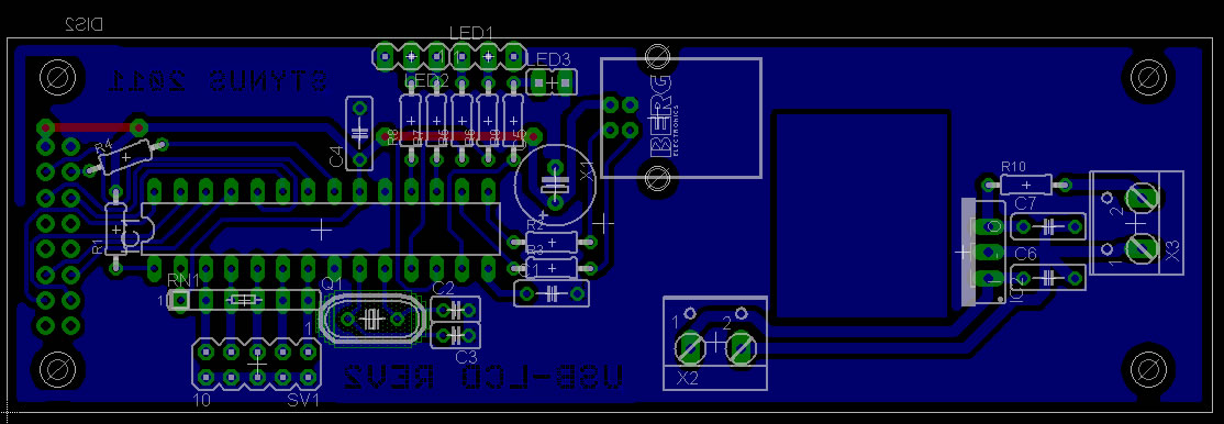
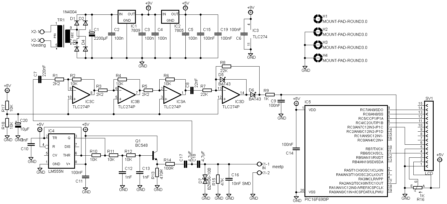
The LCD has to be connected differently. I don’t know why anymore, but here is the new circuit diagram:


I received Eagle files from Predrag Mihajlovic for this esr meter. They can be downloaded here: Link.
Hello,
I did 2 versions. First is one based on your schematics, except that I’ve changed those smd capacitors for standard through hole ones. Second one is somewhat modified. I’ve excluded transformer and put in standard dc jack. Also, pic and display header are located so far away from other stuff so that there is enough place for display to be on the pcb. Also, you’ll see that, on both versions I’ve also put pads for 27 and 22mm capacitors (4.7uF). Check it out and feel free to make any modifications you think are necessary. You can put it on your website if you like, maybe someone will find it useful πŸ™‚
Peca.

IN-14 Nixie Clock – Update

At request I changed the code to a 12h version. However the time still needs to be entered in 24h mode because there is no AM/PM indicator, otherwise it can happen that the date jumps forward at noon instead of midnight.

12h code: Download.