I finished a part of the Z-axis. Now I can mount it to the Y-axis. However it is not completely finished but I quit for today :p.


Apr 03 2007
I finished a part of the Z-axis. Now I can mount it to the Y-axis. However it is not completely finished but I quit for today :p.
May 28 2007
I made the power supply and mounted it in the case:


Jul 05 2007
The capacitors in the previous update can handle max 40V. I didn’t think it was enough because the power supply delivers 36V. Therefore I bought 4 new capacitors of 4700µF 50V and mounted them on a pcb:

Build in and connected:


I’ve cut the back of an old pc power supply to close the back of the case. Now I have a power connector and fan to at once :).

Sep 20 2007
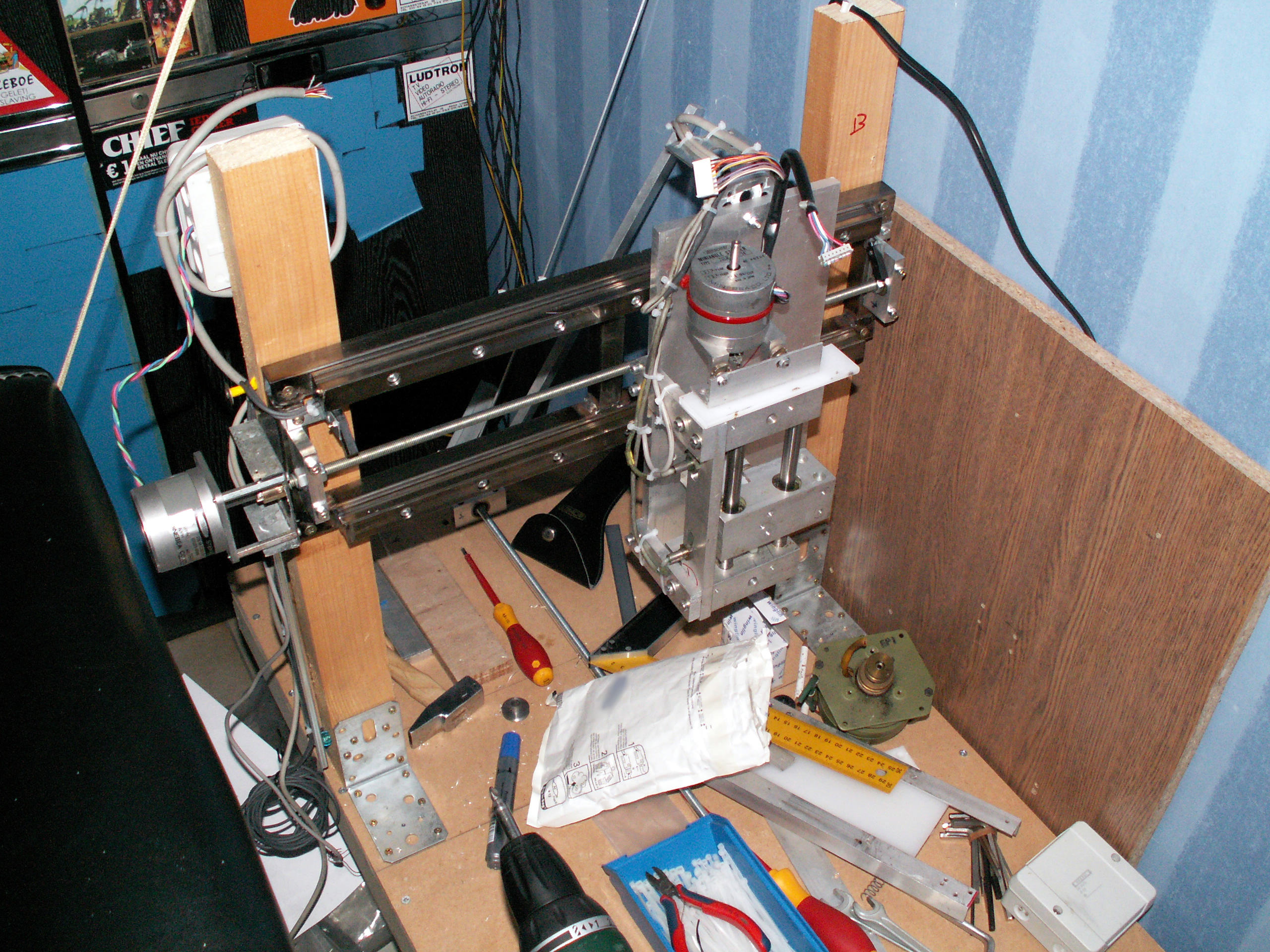
I made some progress on the Z-axis. First I mounted the spindle on the stepper, then I mounted a junction box on the stepper and made a nut from plastic

I also mounted the inductive sensors:

Detail of the coupling between the spindle and the stepper:

The plate to mount a Dremel or equivalent on:
Jun 18 2008
Today I mounted an aluminium plate to my Z-axis for the connection between the Z and X axis. Then I made some slide bearings for on the rails of the Y-axis. The slide bearings are mounted on the back on the aluminium plate.


Jun 20 2008
The last couple of days I’ve been busy making a table for my cnc. I already mounted the Y-axis.


Jul 29 2008
I have received another set of bearing holders (Thanks Jaak!!). Yesterday I mounted 2 off them at the Y-axis and I made another nut from plastic. I also made a bracket from some scrap rvs to mount the stepper. The coupling with the spindle is made from a piece of scrap brass with some bolts.

To protect the axis I’ve put some inductive end sensors on it, and on the back I’ve made a cable duct for the cables from the Z-axis.

Aug 21 2008
I made another 2 stepper drivers:
Yesterday I made a new motherboard. The old 1 had a few design flaws in it. The new one is for 4 axis so I don’t need to build another one if a forth axis is added.
Circuit:

Pcb:

Partlist:
|
Name:
|
Value:
|
|---|---|
| R1, R2, R3, R4 | 4K7 |
| R5, R6, R7, R8, R9, R10, R11, R12 | 470R |
| R13, R14, R15, R16 | 330R |
| R17, R18, R19, R20 | 3K3 |
| C1 | 4700µF |
| C2, C3 | 100n |
| D1, D2, D3, D5 | 1N4004 |
| IC1 | ULN2803 |
| IC2 | 7805 |
| LED1, LED2, LED3, LED4, LED5, LED6, LED7, LED8 |
LED groen 5mm |
| LED9, LED10, LED11n LED12 | LED rood 5mm |
| OK1, OK2, OK3 | PC849 |
| TR1 | Transformer 1.5VA 9-20V |
| X1 | 25p sub-d connector |
| X2, X3, X4, X5 | 3p printkroonsteentje |
| X6 | 5p printkroonsteentje |
| X10 | 2p printkroonsteentje 230V |


Sep 06 2008
I designed the pcb for the stepper driver. It uses an L297 and L298 ic. The circuit I used:

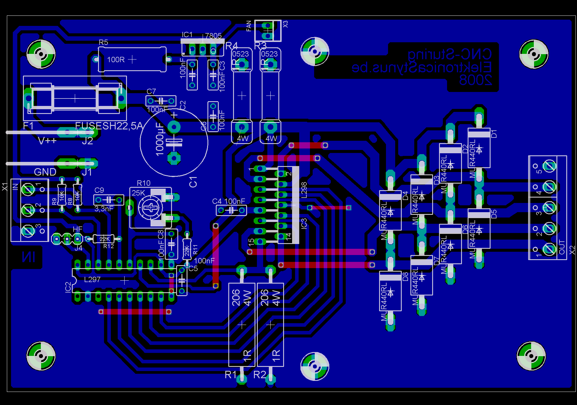
Partlist:
|
Name:
|
Value:
|
|---|---|
| R1, R2, R3, R4 | 1R 3W |
| R5 | 100R 5W |
| R8, R9 | 10K |
| R10 | 25K trim potmeter |
| R11, R12 | 22K |
| C1 | 1000µF 50V |
| C2, C3, C4, C5, C6, C7, C8 | 100nF |
| C9 | 3,3nF |
| D1, D2, D3, D4, D5, D6, D7, D8 | MUR440RL |
| IC1 | 7805 |
| IC2 | L297 |
| IC3 | L298 |
| J1, J2 | AMP vlakstekker |
| J4 | 3p pin header |
| X1 | 3p printkroonsteen |
| X2 | 5p printkroonsteen |
| X3 | fan connector |
| F1 | 4A fuse + holder |
| M1 | 40mm 5V Fan (optional) |


Sep 07 2008
I finished the Y-axis and made a bed from epoxy coated plywood.


I also reinforced the pillars.