Most commented posts
- Resistor Decade Box — 15 comments
- Desoldering Station — 12 comments
- 3D Printer UV Curing Device — 6 comments
- Audio Spectrum Analyzer — 4 comments
- ESR-Meter – Update — 4 comments
May 17 2007
My old power supply didn’t have a current limit and was not protected against short circuit.
This is the second time I change the circuit in this power supply, the previous time I replaced the original circuit by this one:

I changed the circuit to this one because the original burned out after a short on the output terminals.
The case:

I wanted to have a higher output voltage then the original, therefore I used a 2*12V 2*5A transformer I had lying around (bought it at a garage sale).
The ciruit I’m going to use this time:

Source.
The display print covered the entire front off the power supply. Because of that there was no space to put an extra potmeter to regulate the current, so I decided to build new voltage and current meters.
The circuit that I used for that:
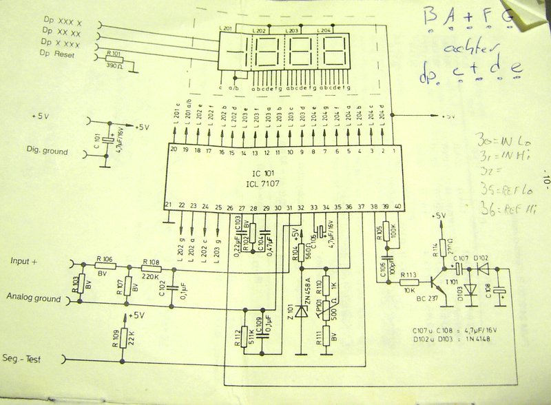
For the missing resistor value’s see: fig. 1 en fig. 2.
Source.
Datasheet ICL7107.
May 17 2007
I was planning to buy a function generator, but those things are too expensive so I decided to build one myself. I based my design on a project from “EPE Electronics“. The output from this design can’t deliver much current, so I’m going to build a amplifier that can drive a 50 Ohm load.
Pictures:


The front panel design:
May 27 2007
The power supply and capacitor pcb’s are ready:


Printlayout


Printlayout
May 28 2007
I made the power supply and mounted it in the case:


May 28 2007
This is a clock that starts with a selectable amount of leds on. Then every 20min 1 leds goes off.
(Can be used as a sleep timer for autistic kids)


I made a second version of this project. Link
May 28 2007
I have to go to my pc to see which song winamp is playing (I can’t see that from my worktable). For this reason I have decided to make an LCD above my worktable and control it with “LCD Smartie“. Normally this is done with a parallel port, but then I had to lay a “big” cable to my worktable, while there was already an USB hub op my worktable. So I went for an USB LCD. The design for this I found on bit-tech.
For the LCD I’m going to use an 2×24 LCD that i got from Mario:

The circuit:
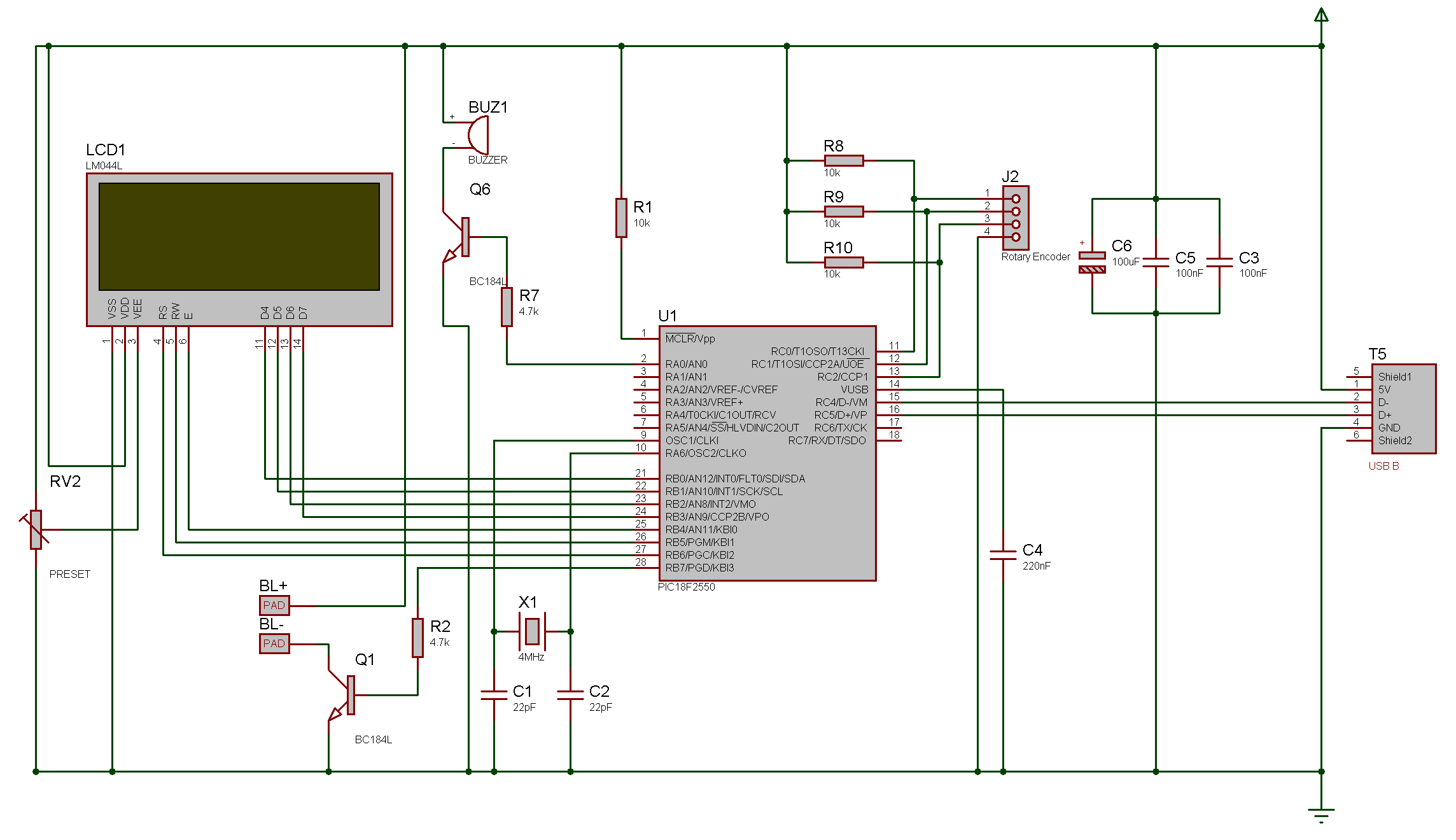
Source. 18F2550
Jun 06 2007
I mounted a new heat sink because the old one wasn’t big enough.


(The bracket is used to press a TO-220 heat sink to the head of the transistor for some extra cooling)
The supply for the panel meters had to be isolated from the main power supply, so I build a small pcb with 2 7805 powersupplies.


Mounted:


Jun 12 2007
This twilight switch works a bit different then a normal one. It turns the output on when there is sun. The purpose for this is to power a water pump to pump water trough a hot water solar panel. If you let it run at night it will cool your water back down.
Circuit:
The pcb lay-out:
With components
Without components


Plug to the LDR


