I finished a part of the Z-axis. Now I can mount it to the Y-axis. However it is not completely finished but I quit for today :p.


Apr 03 2007
I finished a part of the Z-axis. Now I can mount it to the Y-axis. However it is not completely finished but I quit for today :p.
May 28 2007
I made the power supply and mounted it in the case:


Jul 05 2007
The capacitors in the previous update can handle max 40V. I didn’t think it was enough because the power supply delivers 36V. Therefore I bought 4 new capacitors of 4700µF 50V and mounted them on a pcb:

Build in and connected:


I’ve cut the back of an old pc power supply to close the back of the case. Now I have a power connector and fan to at once :).

Sep 20 2007
I made some progress on the Z-axis. First I mounted the spindle on the stepper, then I mounted a junction box on the stepper and made a nut from plastic

I also mounted the inductive sensors:

Detail of the coupling between the spindle and the stepper:

The plate to mount a Dremel or equivalent on:
Oct 21 2007
This update is not from today but from the past year. I have done a couple of small changes and didn’t post them on the site at that time. Now it is time to finely do that.
The first change was that I mounted the transformers in the other direction. This way I’m saving space and I have wound some extra coils at 2 transformers to power the logic.
A picture of how the power supply looks like at the moment

I also decided that I’m going to use rotary encoders instead of touch ic’s. Therefore I ordered some rotary encoders at Sure Electronics. I’m going to use 4 of them in this power supply.


Mar 26 2008
I received 2 transformers (2x30V 750VA) that I bought on Kapaza. 1 of those 2 I’m going to use for this project.

Jun 18 2008
Today I mounted an aluminium plate to my Z-axis for the connection between the Z and X axis. Then I made some slide bearings for on the rails of the Y-axis. The slide bearings are mounted on the back on the aluminium plate.


Jun 20 2008
The last couple of days I’ve been busy making a table for my cnc. I already mounted the Y-axis.


Jul 10 2008
I decided to build a enclosure myself because the old enclosure above is not pretty enough. I’m also going to replace the heat sink by 2 larger ones that I bought on a radio market.
The heat sinks will form the side’s of the new enclosure. The rest will be made from aluminium sheet.

Jul 17 2008
I bought some bigger heat sink for cheap. (Thanks Ben and Robert). I have put those new heat sinks on this power supply. With this heat sink it doesn’t need a fan, because the ribs run in the other direction and the heat sink is much bigger. I cut 5cm of the case at the back and mounted the heat sinks. In the middle I’ve put a panel for the power connector and in the future a usb connector.


I also made a new switch pcb because I was not happy anymore with the old design. The triacs to switch the 230V side of the transformers are driven by an PIC12F629. I have put a low power powersupply on this pcb to generate 2*5V from the extra windings I made around the transformers.

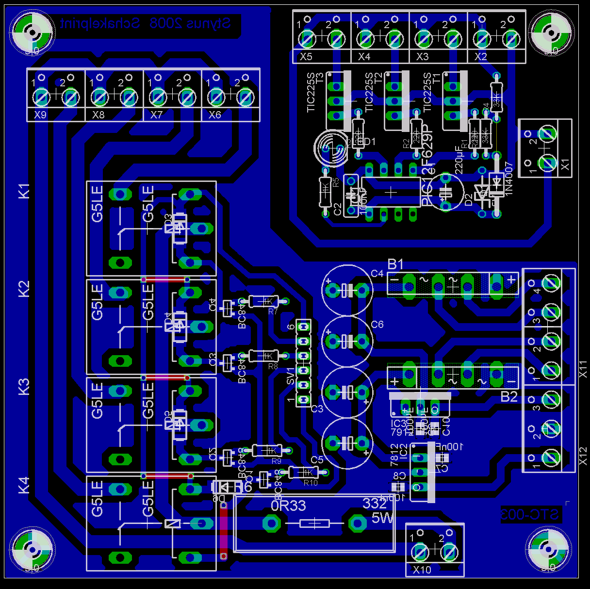
Partlist:
| R1, R2, R3 | 220R |
| R4, R11 | 33K |
| R6 | 0R33 5W |
| R5 | 3K3 |
| R7, R8, R9, R10 | 1K |
| C1 | 470µF 25V |
| C2 | 100nF |
| C3, C4 | 10µF 25V |
| C5, C6 | 1000µF 25V |
| C7, C8, C9, C10 | 100nF SMD 0805 |
| D1 | 1N4007 |
| D2 | 5V1 |
| D3, D4, D5, D6 | 1N4007 SMD |
| B1, B2 | rectifier |
| IC1 | PIC12F629 (Code) (Hex) |
| IC2 | 7812 |
| IC3 | 7912 |
| K1, K2, K3, K4 | Relays |
| LED1 | LED 5MM red |
| Q1, Q2, Q3, Q4 | BC848 SMD |
| T1, T2, T3 | TIC206D |


