Category: Power Supplies

12V AC Power Supply

In a lot of electronics I bought there was a small variac. Unfortunately I could not find a datasheet, but after some experimentation I found out it was for 12V AC. Laying on the shelve it was quite useless, so I decided to make an low voltage AC power supply with it.

To determine the max input voltage, I measured the zero load current and put it with the input voltage in a graph:

From this graph I concluded that as long I stay below 15V saturation is not a problem. Therefore I have chosen to use it on 12V.

I build it in enclosure together with an 12V halogen transformer. Also I readout based on that of my Safety transformer V2 & Safety transformer V3, the version in this project however is adapted to measure lower voltages, so the resolution increases. Also a power supply for the meters is added.

Complete unit:

12V 25A PowerSupply

To test my LED Stair Lighting Controller boards I needed a 12V power supply that can deliver a lot of current. For this I chose a SP-320-12 from meanwell. However with the screw terminals it is not easy to use on a lab bench, also there is no display to monitor the output current. Therefore I build an enclosure around the PSU, and added a volt and ampere meter.

The meter I chose was a cheap one from AliExpress: DC 0-100V 30A 50A Dual Digital Voltmeter Ammeter Panel with DC 50A/75mV Shunt LED Red Display


Everything mounted in the enclosure (Hammond 1598JSGYPBK):

To limit the voltage drop of the wiring I used a lot of wires in parallel, and braided them to keep them close together:

Front panel connections:

The banana connectors are special ones that can handle 25A. (Red: Farnell 1698956 and Black: Farnell 1698957). Standard ones would probably melt in this use case.

In the back of the enclosure I have made some holes for the air to get in the enclosure, on top of the fan of the PSU I made a air duct to the top of the enclosure. In the top lid I made holes for the airflow to exit.

Front-panel:

Delta Elektronika 0-15V 15A +5V 13A PSU

Sometime ago I received 2 Delta elektronica power supply’s from a colleague. One is 0-15V  15A and the other one is a fixed voltage of 5V at 13A max. The first one is defective, and the second one brand new.

So lets start with the investigation on what is wrong.

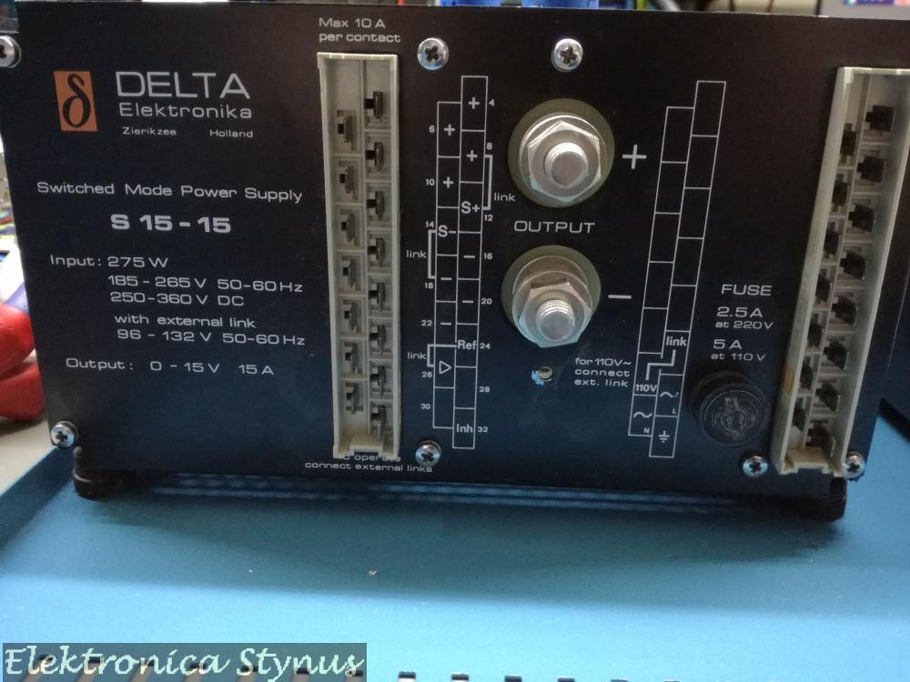
The output voltage of the power supply is 0.5V. I know that sometimes on these power supply’s the crow bar fails, so I disabled this circuit and still 0.5V max on the output. In the mean time I received the schematics, this helps a bit in the search. This way I could check the switching signals, everything looked ok, but then I found that the voltage is being held back by the current limit. This should not happen since the potmeter is wide open. After some more searching this was caused by a broken zener diode.
Hurray it works now, well not exactly, it does make voltage, but almost no power. This was caused by an undocumented extension in the power supply, this connected 2 wires to unused pins in the connector. After shorting these the power supply worked. So I connected it to a 1R resistor, 15V 15A everything worked, switched it off, back on again. 0V on the output, hmm the zener is still good, wire connected. The during the analyses I noticed that the AC input of the power supply varied with the current limit. Hmm, so it is producing power. A resistance measurement on the output told me it was 0 Ohm, even with no load connected. Aha, this should not be. It should be a diode I thought, wrong. It was 1 of the elcaps that was a dead short. After replacing these everything worked again. However replacing these was also not straight forward, these antique form factors were not sold any more, so I pried the foots off and soldered the new caps to them. Not having the exact values I needed 4 caps on the footprint of 3.

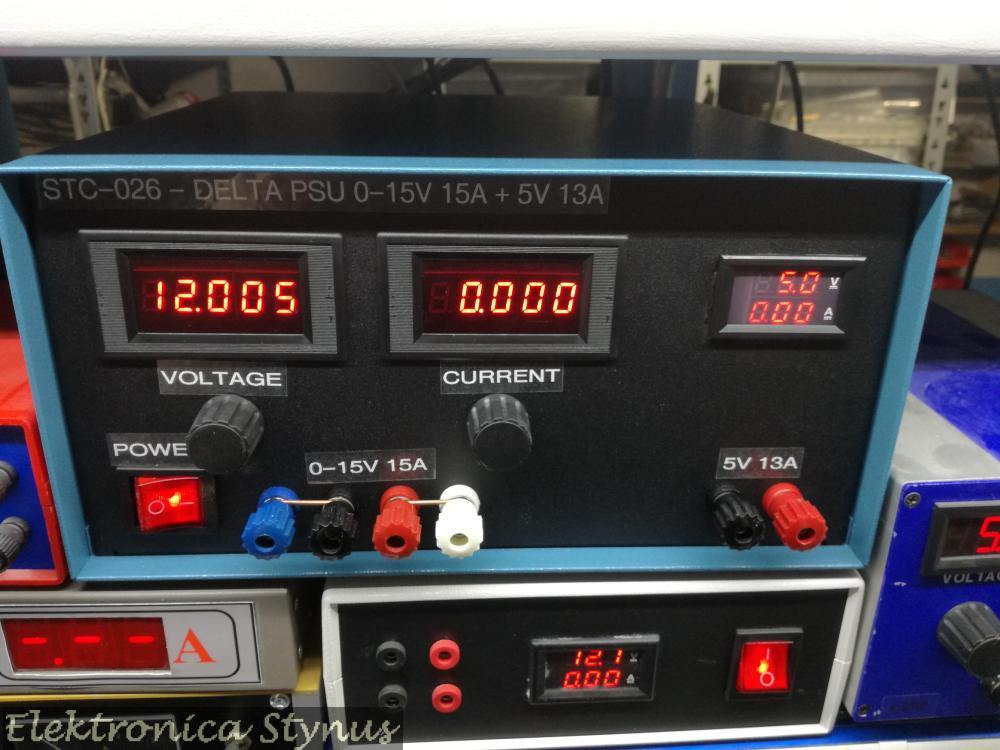
After this the project got a whole lot easier. I removed the internal potmeters, soldered wires to the pads and installed external ones. Together with the other power supply and the meters it then looked like this:

Some more pictures:

The front plate:

I’m not happy with the labelling, so this needs to be changed later on. But for now the power supply is installed on the shelve with the rest of the equipment until I have time to update the labelling and know how I want to do it. If you have a good suggestion, please leave it in the comments below.

Delta Elektronika 0-15V 15A +5V 13A PSU – Update Frontpanel

A few months back I posted this power supply project. However I was not happy about the way the front panel looked with the labels, but had no inspiration on how to make it better at that time.

In the mean time I bought a new 3d printer. This one prints a lot better than my other ones, and this gave me some idea’s and after some experimenting I printed this front panel. It is made of first 3 layers printed in black and then where the letters background starts the filament is changed over to white.
The front is made in 2 pieces since the width is too much for the printer bed.
This gives the following result:

Lab power supply 0-24V 0-2A DC

I’m finishing some old projects. One of these project is a lab powersupply based arround a kit I bought on AliExpress.

I had a old transformer from a crt screen that outputs 22V at enough power (does not get hot at full load) and as a bonus has shielding on the outside. For the enclosure I used an enclosure of a 230->110V transformer that I got very cheap at an auction some time ago. The front and back panel are 3D printed

The heatsink I used is from a I5 pc. The fan is a 12V fan that makes too much noise. Thats why I put a 5V regulator in series, that regulator is also mounted on the heatsink because it will get hot. The fan is switched with a clixon contact near the transistor.

When the enclosure is closed, the power supply looks like this:

Dual Lab Power Supply 0-48V 0-3A DC

Although having made more than enough power supply’s, there where still some boards in my storage that I bought from a fund raiser at Circuits Online. These are a dual 0-34V 2,5A PSU with tracking. It would be a waste to have the boards and not build them.

(Above pictures are from CircuitsOnline because I forgot to take pictures myself)

As with the previous PSU build kit (Lab Power Supply 0-70V 0-3A) I was not completely happy with the specs (/wanted to make it more of a challenge) and decided to change them to 2x 0-48V 0-3A. This would mean the transistors had to dissipate a lot more heat. To counter this I used a switch mode power supply instead of a normal transformer. This switch mode power supply I modded so It can be controlled by a 0-1.5mA signal to give 20-60V on the output. This way the voltage on the transistors is limited to 20V max. I made a circuit to keep te input voltage about 10V higher then the output voltage.
This circuit I build using 1 of the op-amps on the main board and a small piece of pcb added fixed to a unused connector.

After this the power supply needs to  be changed. Some components can not handle the larger voltage, some resistors need to be adjusted to increase the range and some other modifications have to be done.

Now that the PSU works, it was time to make an enclosure. I could not really find what I was searching for, so I decided to 3D print the entire enclosure. This way it is exactly to size and I can add custom features, like  the front is on a big printed hinge, making it easier to work / measure on the boards.

On the bottom are 3 power supply’s (2x modded 48V SMPS, 1x 12V for the fans), 4x 12V transformer for auxiliary voltages of the supply circuits.

Above this level are the heat sinks, for this I used old processor coolers, where the transistors are clamped on with a  metal sheet. The fans on these heat sinks can be PWM controlled, so I used a simple dev board (the blue one in the centre) to read out 2 temperature sensors and drive 2 fans.

In the front are the 2 lab PSU boards, and on the front panel the display/pot PCB’s:

The end result:

On the equipment shelve: