Category: Projects

Dust extraction – Part 1: Valves

In my workshop I have a lot of machines producing dust / chips. In order to not make the complete house / workshop dirty I connect a vacuum cleaner with cyclone to the machines. The downside of this is that every time I switch machine I also need to disconnect the dust collection hose and connect it to the different machine. To solve this inconvenience I decided to make a central dust extractor with fixed tube to all machines. Each machine will get a valve that can be opened or closed to get the suction to a machine.

For the valves I did some research , and I found that a lot of people use sliding gates for their dust valves. For example:


(Source: Reddevil on Schematheek.net)

I did not like the fact that these take up too much space. So I opted for a design that looks more like a ball valve. However a bit different, so I could 3D print it. I found some central door lock actuators for cars on my desk and thought of a concept to operate the valves with these.

A first test:

This was made for a 40mm pipe, the dimensions of the moving parts where not very good yet and it got stuck sometimes. After this test I decided to use 50mm pipe for the dust collection, the linkages etc I reused from the 40mm and it turned out to work very good. The only downside is that the valves only open to ±70%,. But for the small chips / dust that goes trough I do not expect any problems.

Valves assembly:

The next part of this project will be a current sensor unit.

Dust extraction – Part 2: Current sensor

In this part of the dust extraction build I will show the current sensor. This sensor measures the current that the tool draws and gives a signal to a central unit once it is higher than a set value. In order to leave the vacuum cleaner on during the machine spinning down a settable timer is added. Also I added a start stop circuit, witch can be used to manually start/stop the valve and vacuum.  This can be handy to clean the work table. These buttons are not placed on all sensor units.


This unit consists of 2 parts.

Part 1: the current sensor:

A current transformer (ASM-010) is placed around the live wire.

The output of this transformer is send trough a 50R resistance. This converts the output current of the clamp to a voltage. This voltage is then amplified and compared against a level set by the potmeter. After this a 555 timer is added to keep the suction active while the machines motor spins down.

Part 2: on / off buttons:

This part works with a set reset flipflop. This has 2 buttons connected to manually start / stop the dust extractor.

Total:

The output of the 2 parts are coupled together with 2 diodes to a transistor that pulls the interface line to the controller low when it wants to turn on the dust extractor.


The PCB I designed for this project:

In order to keep the potmeters in place I added a small 3d printed bracket.

Build in the enclosure:

Links to previous parts of this build:
Dust extraction – Part 1: Valves

The next part of this project will be the central unit.

Steinel Gluematic 3002 – Modification [Part 2]

I bought a longer nozzle for the glue-gun in order to reach further in difficult places. This works great, but the downside is that now the stand is not high enough any more and the nozzle touches the table.

While searching for something on thingeverse I came across this project: https://www.thingiverse.com/thing:2739665  This seems like the perfect solution. 1 hour of printing later I had the piece:

Mounted on the glue gun:

Part 1 in this series

Dust extraction – Part 3: Central Unit

In this part of the dust extraction build I will show the central unit. This unit receives the signals from the current sensor boxes and uses this information to switch the valves and the vacuum cleaner.

Some time ago I designed a board with a pic processor that has robust in and outputs. These have protections similar to a PLC has.

To drive the valves a lot of current is required, more than this board can drive, also more outputs are needed. Therefore I bought a 16 channel relay board.

This relay board needs 16 signals to drive the relays, unfortunately the board I use only has 8 outputs, of which 1 is already taken by the vacuum cleaner. Therefore I designed a board around 2x 74HCT595 IC’s to drive the relay board. To make the board also useful for other applications I added ULN2803 drivers to each output, however they are not used in this project.

There are optocouplers on the relay board in the drive path of the relays. They invert the signals. I do not want this, so I removed these and replaced them with 0 Ohm resistors.

The inputs I have on the controller board are made for PNP sensors, however the sensors have a NPN on the output.  This I fixed by putting pullup resistors on the inputs. However this makes the signals come in the microcontroller inverted, but this is easy fixed in the firmware.

All boards mounted / wired to contact strips:

Next to the dust extraction controller I also build the power supply + power distribution strips for the LED strips. To provide music in the workshop I also fitted an audio amplifier in this enclosure.

Amplifier

Links to previous parts of this build:
Dust extraction – Part 1: Valves
Dust extraction – Part 2: Current sensor

The next part of this project will be the solid state relay.

Dust extraction – Part 4: Solid State Relay

In this part of the dust extraction build I will show the solid state relay that is used to drive the vacuum cleaner.

I could make this part of the project with a PCB with a triac and optoupler etc, but decided not to do this to save time. Instead I used an off the shelf SSR-40DA solid state relays.

During use this component will get hot, therefore I mounted it to the side of an aluminium enclosure. In this enclosure I also mounted a grommet for the power input, a grommet for the signal wire and a power socket for the output.

Inside soldid state relais module
Inside soldid state relais module detail
SSR front panel

The box mounted near the vacuum cleaner:
SSR Mounted

Links to previous parts of this build:
Dust extraction – Part 1: Valves
Dust extraction – Part 2: Current sensor
Dust extraction – Part 3: Central Unit

The next part of this project will be the instalation of the tubes / hoses

12V 25A PowerSupply

To test my LED Stair Lighting Controller boards I needed a 12V power supply that can deliver a lot of current. For this I chose a SP-320-12 from meanwell. However with the screw terminals it is not easy to use on a lab bench, also there is no display to monitor the output current. Therefore I build an enclosure around the PSU, and added a volt and ampere meter.

The meter I chose was a cheap one from AliExpress: DC 0-100V 30A 50A Dual Digital Voltmeter Ammeter Panel with DC 50A/75mV Shunt LED Red Display


Everything mounted in the enclosure (Hammond 1598JSGYPBK):

To limit the voltage drop of the wiring I used a lot of wires in parallel, and braided them to keep them close together:

Front panel connections:

The banana connectors are special ones that can handle 25A. (Red: Farnell 1698956 and Black: Farnell 1698957). Standard ones would probably melt in this use case.

In the back of the enclosure I have made some holes for the air to get in the enclosure, on top of the fan of the PSU I made a air duct to the top of the enclosure. In the top lid I made holes for the airflow to exit.

Front-panel:

3D Printer UV Curing Device

Some time ago I bought another 3D printer, this time one that uses resin to print. However after printing the parts are not full strength yet. To solve this the parts need to be put in UV light. This can be done outside in the sun or in an UV curing device. Since the sun does not always shine when I’m printing I decided I need a UV curing device.
I did some research on this, but only saw devices that where either much too expensive, or the quality too low or very unpractical. At this time I was thinking why not convert an old microwave oven. It has a rotating disk to put the prints on, it has a timer and it is nice and enclosed.

After asking around I got a defective microwave oven. The tube was defect. However this does not matter for my use-case since I replaced the MOT and tube with a LED driver and UV LEDs.

Now in theory it should already work, but I wanted to make it more custom. I saw that the driver board contained an old PIC16C65B microcontroller. This is a one time programmable, so I replaced it with an (also old) PIC16F877A. Now the timer can be equipped with custom firmware.

Only now the difficult part started. The pins that go to the 7 segment displays do not only drive the displays, they also read out the switches. This took a lot of searching and reverse engineering of the circuit board. I do not have a full schematic off it since I only did what was needed. But I did make a sketch to make this more clear:

The code I wrote for the microcontroller:

The result:

Please accept YouTube cookies to play this video. By accepting you will be accessing content from YouTube, a service provided by an external third party.

YouTube privacy policy

If you accept this notice, your choice will be saved and the page will refresh.

Air Compressor Remote / SwitchClock

I have a loud air compressor in my basement. Lots of time I forget to turn it off, and the in the middle of the night the air pressure leaked enough so that it switches on. Another annoying thing is when I remember to turn it off, I need to walk to the compressor to turn it back on when I need it. Therefore I want to automate it a bit, with a controller / remote control.

What I want this system to do:

  • Switch off at 23h00, but it should not automaticity switch back on, for this it requires user input.
  • A remote control within reach of each air outlet.
  • Some sort of pressure readout at the air outlets.
  • A mode that turns the compressor on only once, so that it switches completely off again when the set pressure is reached.
  • To ensure safety all the above without touching the existing protections of the compressor.
  • Wired remote controls


For this I designed a pcb with a PIC microcontroller. With the long wires all inputs have individual filtering to prevent noise switching the compressor on or off. This made the pcb to be full of small components.

The board:

These board contains:

  • 7 RJ45 connections for the remote control boards
  • Compressor current measurement (to detect if the motor switched off)
  • Pressure sensor input (Is translated to red->green light on a RGB LEDs on the remotes)
  • LCD connection
  • Realtime clock
  • Button interface for menu
  • 12V power supply
  • Drive circuit for an external relays

Schematic:

For the remotes I made some boards that fit in a 3d printed piece designed to go in a Legrand dlp cable tray.

Schematic:

The controller board is build in an enclosure with transparent front:

Demonstration video:

Please accept YouTube cookies to play this video. By accepting you will be accessing content from YouTube, a service provided by an external third party.

YouTube privacy policy

If you accept this notice, your choice will be saved and the page will refresh.

Firmware download: Compressor_Remote_FW_V1_0

Delta Elektronika 0-15V 15A +5V 13A PSU

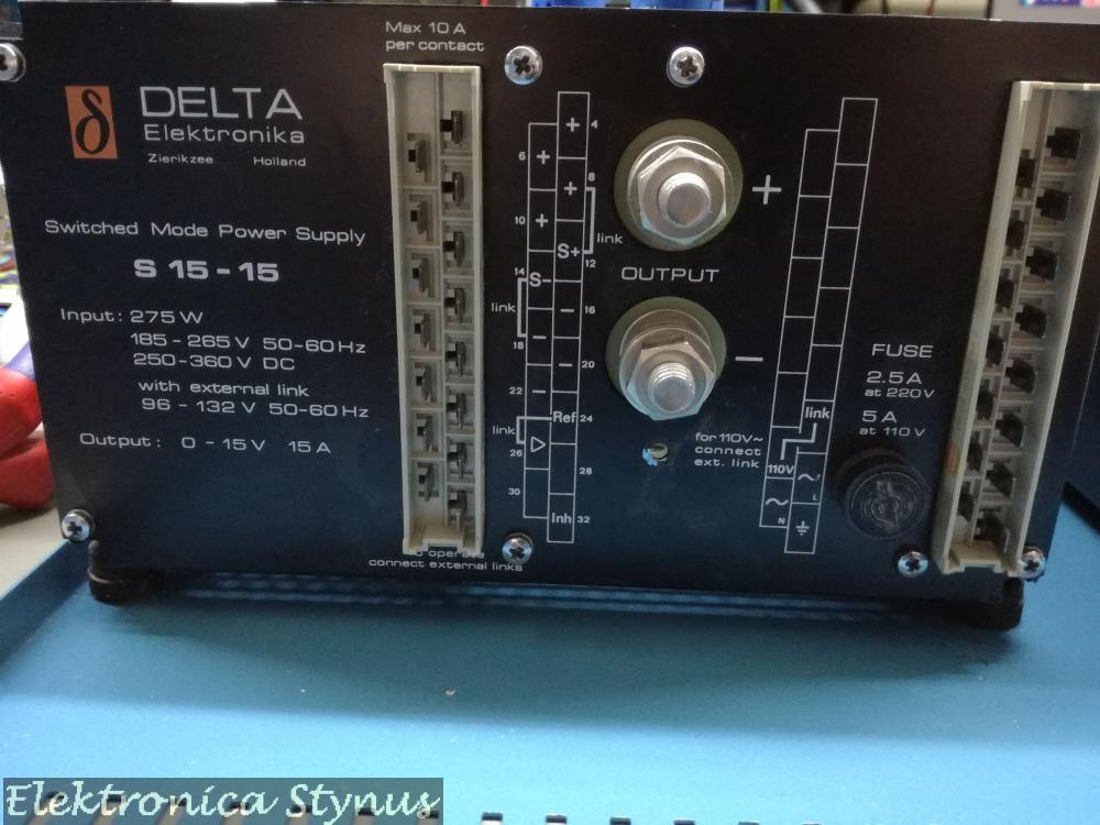
Sometime ago I received 2 Delta elektronica power supply’s from a colleague. One is 0-15V  15A and the other one is a fixed voltage of 5V at 13A max. The first one is defective, and the second one brand new.

So lets start with the investigation on what is wrong.

The output voltage of the power supply is 0.5V. I know that sometimes on these power supply’s the crow bar fails, so I disabled this circuit and still 0.5V max on the output. In the mean time I received the schematics, this helps a bit in the search. This way I could check the switching signals, everything looked ok, but then I found that the voltage is being held back by the current limit. This should not happen since the potmeter is wide open. After some more searching this was caused by a broken zener diode.
Hurray it works now, well not exactly, it does make voltage, but almost no power. This was caused by an undocumented extension in the power supply, this connected 2 wires to unused pins in the connector. After shorting these the power supply worked. So I connected it to a 1R resistor, 15V 15A everything worked, switched it off, back on again. 0V on the output, hmm the zener is still good, wire connected. The during the analyses I noticed that the AC input of the power supply varied with the current limit. Hmm, so it is producing power. A resistance measurement on the output told me it was 0 Ohm, even with no load connected. Aha, this should not be. It should be a diode I thought, wrong. It was 1 of the elcaps that was a dead short. After replacing these everything worked again. However replacing these was also not straight forward, these antique form factors were not sold any more, so I pried the foots off and soldered the new caps to them. Not having the exact values I needed 4 caps on the footprint of 3.

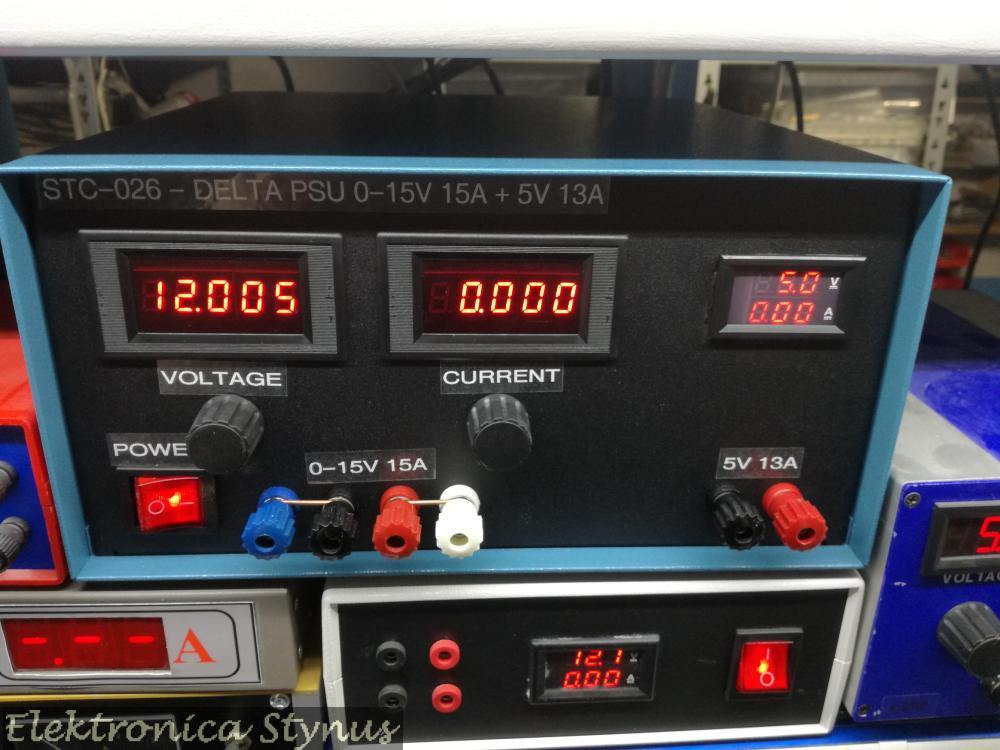
After this the project got a whole lot easier. I removed the internal potmeters, soldered wires to the pads and installed external ones. Together with the other power supply and the meters it then looked like this:

Some more pictures:

The front plate:

I’m not happy with the labelling, so this needs to be changed later on. But for now the power supply is installed on the shelve with the rest of the equipment until I have time to update the labelling and know how I want to do it. If you have a good suggestion, please leave it in the comments below.

Delta Elektronika 0-15V 15A +5V 13A PSU – Update Frontpanel

A few months back I posted this power supply project. However I was not happy about the way the front panel looked with the labels, but had no inspiration on how to make it better at that time.

In the mean time I bought a new 3d printer. This one prints a lot better than my other ones, and this gave me some idea’s and after some experimenting I printed this front panel. It is made of first 3 layers printed in black and then where the letters background starts the filament is changed over to white.
The front is made in 2 pieces since the width is too much for the printer bed.
This gives the following result: