Most commented posts
- Resistor Decade Box — 15 comments
- Desoldering Station — 12 comments
- 3D Printer UV Curing Device — 6 comments
- Audio Spectrum Analyzer — 4 comments
- ESR-Meter – Update — 4 comments
Jun 20 2021
I have a loud air compressor in my basement. Lots of time I forget to turn it off, and the in the middle of the night the air pressure leaked enough so that it switches on. Another annoying thing is when I remember to turn it off, I need to walk to the compressor to turn it back on when I need it. Therefore I want to automate it a bit, with a controller / remote control.
What I want this system to do:
For this I designed a pcb with a PIC microcontroller. With the long wires all inputs have individual filtering to prevent noise switching the compressor on or off. This made the pcb to be full of small components.
The board:


These board contains:
Schematic:


For the remotes I made some boards that fit in a 3d printed piece designed to go in a Legrand dlp cable tray.


Schematic:

The controller board is build in an enclosure with transparent front:


Demonstration video:
Please accept YouTube cookies to play this video. By accepting you will be accessing content from YouTube, a service provided by an external third party.
If you accept this notice, your choice will be saved and the page will refresh.
Firmware download: Compressor_Remote_FW_V1_0
Oct 25 2021
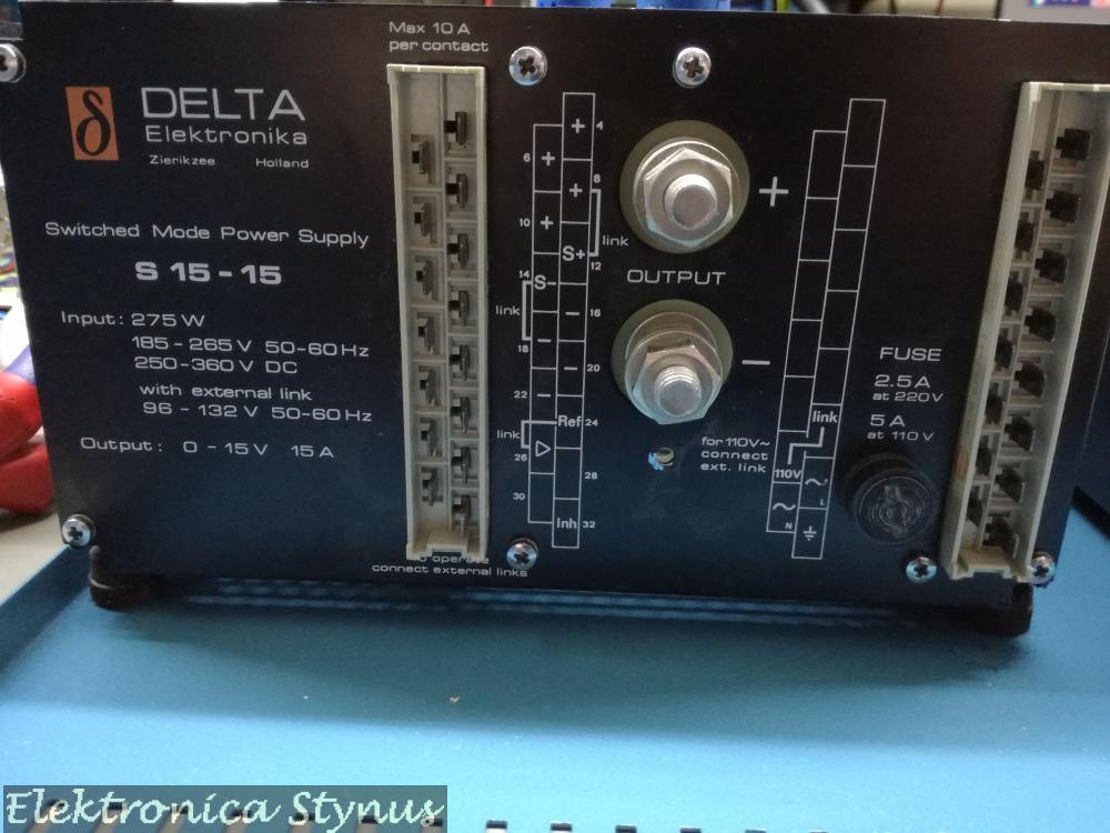
Sometime ago I received 2 Delta elektronica power supply’s from a colleague. One is 0-15V 15A and the other one is a fixed voltage of 5V at 13A max. The first one is defective, and the second one brand new.
 So lets start with the investigation on what is wrong.
The output voltage of the power supply is 0.5V. I know that sometimes on these power supply’s the crow bar fails, so I disabled this circuit and still 0.5V max on the output. In the mean time I received the schematics, this helps a bit in the search. This way I could check the switching signals, everything looked ok, but then I found that the voltage is being held back by the current limit. This should not happen since the potmeter is wide open. After some more searching this was caused by a broken zener diode.
Hurray it works now, well not exactly, it does make voltage, but almost no power. This was caused by an undocumented extension in the power supply, this connected 2 wires to unused pins in the connector. After shorting these the power supply worked. So I connected it to a 1R resistor, 15V 15A everything worked, switched it off, back on again. 0V on the output, hmm the zener is still good, wire connected. The during the analyses I noticed that the AC input of the power supply varied with the current limit. Hmm, so it is producing power. A resistance measurement on the output told me it was 0 Ohm, even with no load connected. Aha, this should not be. It should be a diode I thought, wrong. It was 1 of the elcaps that was a dead short. After replacing these everything worked again. However replacing these was also not straight forward, these antique form factors were not sold any more, so I pried the foots off and soldered the new caps to them. Not having the exact values I needed 4 caps on the footprint of 3.


After this the project got a whole lot easier. I removed the internal potmeters, soldered wires to the pads and installed external ones. Together with the other power supply and the meters it then looked like this:

Some more pictures:
The front plate:

I’m not happy with the labelling, so this needs to be changed later on. But for now the power supply is installed on the shelve with the rest of the equipment until I have time to update the labelling and know how I want to do it. If you have a good suggestion, please leave it in the comments below. 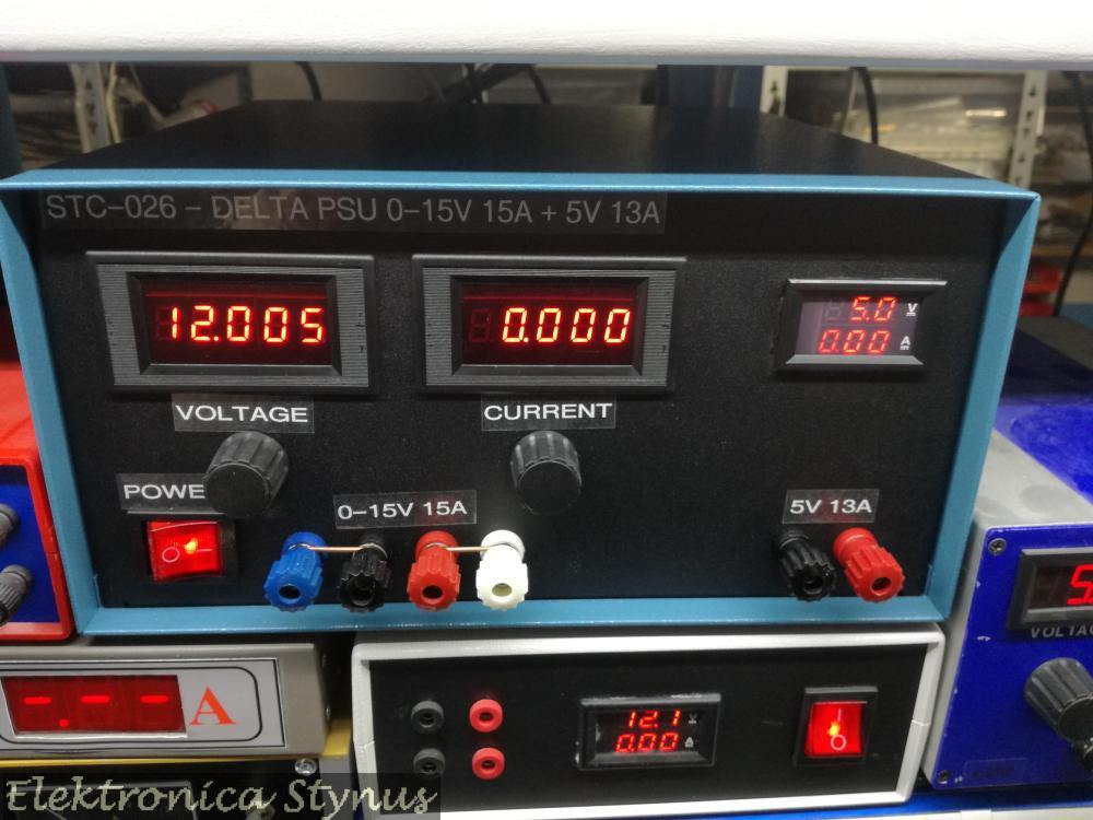
Apr 21 2022
A few months back I posted this power supply project. However I was not happy about the way the front panel looked with the labels, but had no inspiration on how to make it better at that time.
In the mean time I bought a new 3d printer. This one prints a lot better than my other ones, and this gave me some idea’s and after some experimenting I printed this front panel. It is made of first 3 layers printed in black and then where the letters background starts the filament is changed over to white.
The front is made in 2 pieces since the width is too much for the printer bed.
This gives the following result:

Mar 19 2023
After 3 years of not being able to go, or no flea markets happening, I went to a radio market again.
What I bought:

Apr 10 2023
Some time ago I bought a lot of Weller soldering irons at an auction for cheap. For the de-soldering iron I already made a station. In this lot were also a WMRT soldering tweezers cable. Next to that I bought a WMRP iron at a ham flea market. Only problem was that I do not have a station for these. I could buy one, but they are rather expensive.


After some searching for options I came across this site: http://kair.us/projects/weller/index.html I immediately ordered myself a set of boards to make a DIY one.

However I then came to the conclusion that I did not really like having 2 extra boxes on my desk for the stations. I want something that is small and hides somewhere. Maybe underneath the soldering iron stand. So I designed my own board and enclosure to 3d print. A few weeks later the boards came in.

The display and rotary encoder are now on a separate board that mounts at a right angle to the main board. On the back end of the board panel is also a board to mount in the WMRT holder because I suspected it was broken. (Later on I found out it was still ok.)
3D Design:


For both the WMRT and WMRP this part was exactly the same.
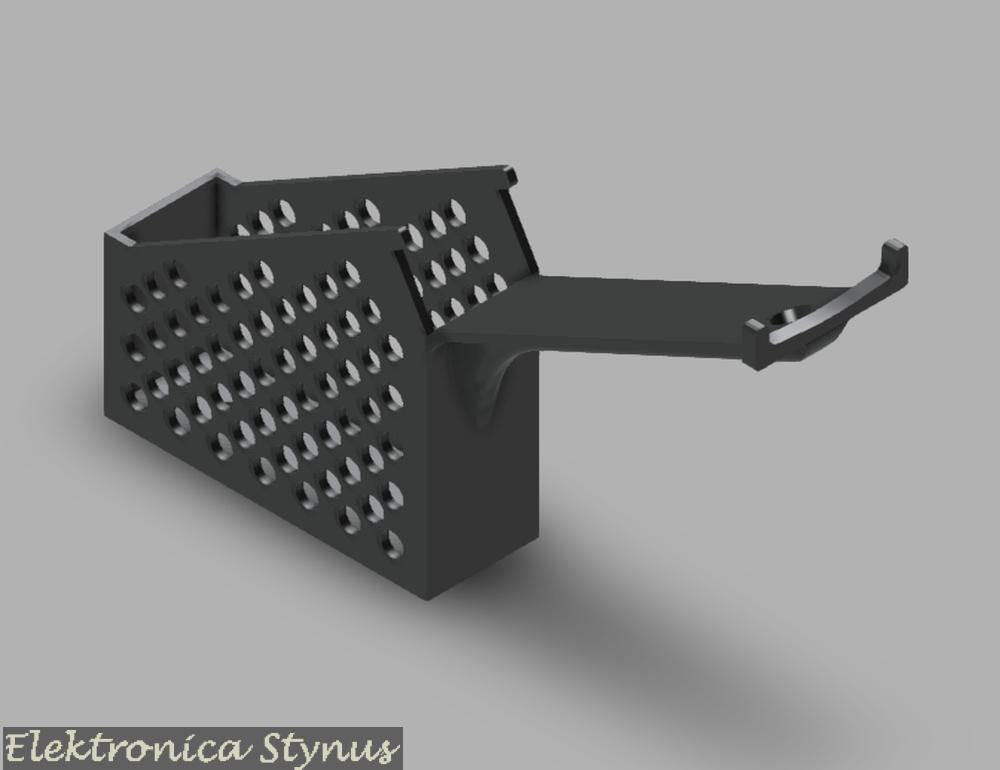
Next part was a holder for the iron. I could either build something out of metal or 3d print it. I chose for the second. The base was printed out of normal PLA since it does not really get hot unless a piece of molten solder falls on it. For the holder it is a different story. I needed a material that can handle high temperatures. This was not easy to find, but I found out that objects made in the resin printer can handle the heat quite well if you do not force the tips into it. Therefore I chose to print these out of resin.
For the WMRT the complete thing is resin with a magnet pushed in. For the WMRP the main part is resin, but the long thin support I made from 6mm² copper wire.
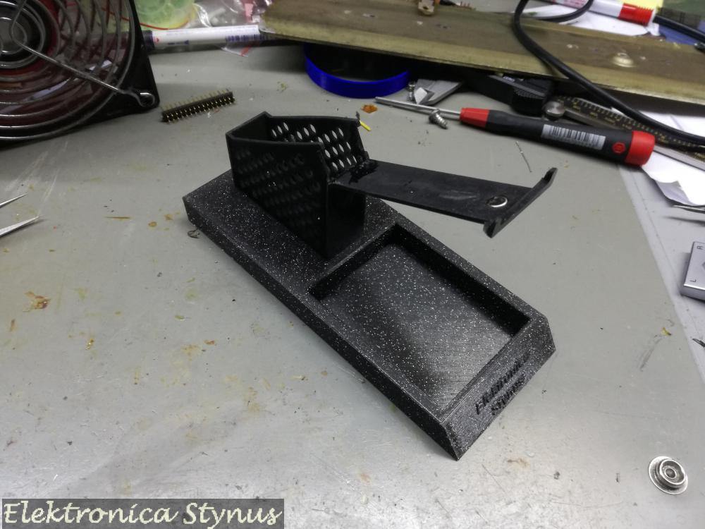
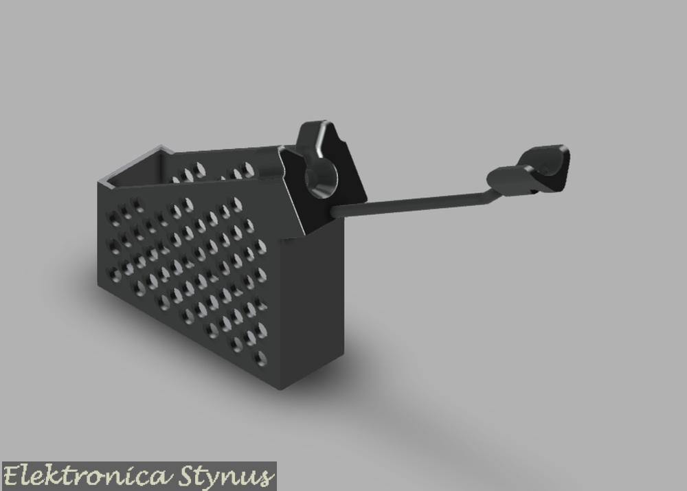

On the bottom of the iron bases I glued some washers. In the station part are some magnets, this makes that the base does not move easy on the station part, but can be detached when needed.
Next I needed a way to connect them to the 12V desk PSU. I also wanted a way to switch them on / off. So another box with switches needed to be build.


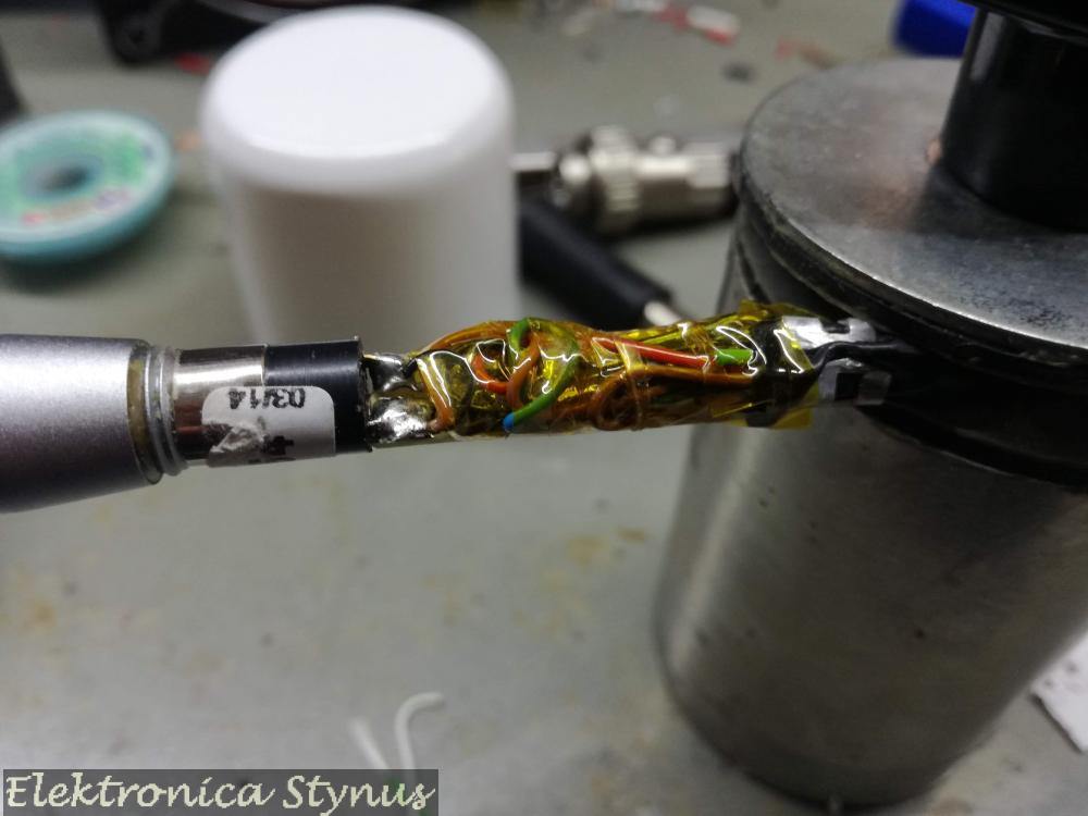
Ok, so now the WMRT works, but the WMRP I found out was not a WMRP but a WXMP. This means that the reed switch is replaced by a hall sensor and a lot of electronics are added. I removed this board and replaced it by a piece of experiment board with a reed switch from a door contact and the KTY 82 temperature compensation.

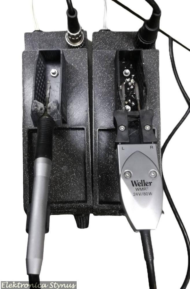
Now my desk looked like this:

As you can see the front of the stations is still open, so this was the next project. For this I used some black mirror transparent plexi. The button was 3D printed.
Off:

On:

Files / Links:
Oct 02 2023
For some time I wanted an camera to inspect solder joints / SMD parts.
What I wanted it to have was:
I found a few options, but they ware either too expensive, or the quality too low. Some time went by and then I came across a camera module at a HAM flea market. This one was not too expensive, but was only a camera module that was open on all sides. Therefore the first job was to design an enclosure. I was inspired by a professional version:


The enclosure I 3D printed in PLA. For the rails I used some old printer guide rails with slide bearings on them.


The left picture is when the camera is not in use. It is pushed completely to the back and the slides are locked in place with a magnet. The other 2 pictures are when it is slide out and in use.
Inside the enclosure it looks like this:


It contains a PCB that receives bus signals, drives the LED ring and forwards messages that are meant for the camera. For the connection of the camera to the PC, it contains a 4ch composite to USB converter (I had this one and did not want to order an extra 1ch version).
The cable that exits the camera enclosure connects to a controller.


With this controller box I can set the zoom level, focus level, intensity of the LEDs and the iris.
In the back panel is a USB plug, this one is connected to the composite to USB converter in the camera. The other input is a 12V power adapter and a programming plug for if I need to make a firmware update.
For the cable between this camera enclosure and the controller used a USB3 cable with the ends cut off. This way I have the 4 usb2 wires and an extra 4 wires for signals and power.
Underneath the camera I made a LED rind to illuminate the area. Under that I made a polarising filter.


With this filter I can change the polarisation angle of the LED ring with respect to the angle of the filter on the camera lens by rotating the polarisation ring. This makes it possible to make text on IC’s visible that would normally be hard to see. For example, below is one picture with the filter at a random angle and then rotated to a good visibility:


More details on the PCB’s:
The LED ring / camera controller board:


Controller Board / 28pin PIC breakout board:


Nov 04 2023
The switch that I use to switch off my hobby desk broke again for the second time. The contacts where welded shut. After replacing it again it was time to fix the cause of the issue. To limit the current I used an altered schematic from CircuitsOnline.

After my incident on my safety transformer project where the resistors burned I did not fully trust this circuit. Therefore I have added a thermal protection that switches the output power off when the resistors get too hot.
I build the circuit in a remote controlled socket enclosure. To mount the parts I used some glue and tyraps.


Dec 16 2023
For some time I had project boxes and storage boxes loose on the floor. Therefore I decided to build 2 cabinets to solve this problem.
First for the sorter boxes I build a cabinet with drawers on the bottom and on top shelves for the boxes. In the big space I put some old drawers.


For my project boxes I made a cart that sits next to my desk. In this I have 5 project boxes. (I will now try to finish my running projects and then limit to 5 projects at the time.) Next to the project boxes is space for SMD storage containers, These are placed on an angle because the cart would otherwise become too wide. On top there is space for 12 storage boxes for frequently used components and parts (Heatshrink, AMP connectors, ferrules, etc.).


Dec 26 2023
I’m finishing some old projects. One of these project is a lab powersupply based arround a kit I bought on AliExpress.

I had a old transformer from a crt screen that outputs 22V at enough power (does not get hot at full load) and as a bonus has shielding on the outside. For the enclosure I used an enclosure of a 230->110V transformer that I got very cheap at an auction some time ago. The front and back panel are 3D printed
The heatsink I used is from a I5 pc. The fan is a 12V fan that makes too much noise. Thats why I put a 5V regulator in series, that regulator is also mounted on the heatsink because it will get hot. The fan is switched with a clixon contact near the transistor.


When the enclosure is closed, the power supply looks like this:


Jan 13 2024
I have a Pioneer XR-A550 hifi system that I use as an amplifier for sound / music from my pc. This works great, however at the end of the day I switch the power of my bench off, this includes the Pioneer. When I switch on the power again the Pioneer has lost all its settings, so I have to enter it in aux mode and turn the volume back up. After doing this for a few years it was time to automate this.
To do this I decided to replicate the IR remote commands with my own circuit. For the board I used a spare board from my Solder / SMD inspection Camera project, this board has a microcontroller and a mosfet to drive a higher current load. So it makes it ideal to drive the IR LED.
The enclosure is 3D printed and is designed to clip onto the aluminium of my LED light.


To get the IR commands I connected a IR receiver to a logic analyser. The signals I then decoded in a spreadsheet and made some quick and dirty code to reproduce them.

The signal for the IR LED needs to be modulated at 38Khz, for this I used a PWM module in the microcontroller. I send duty-cycle 0 for off and 50% for on. LATAbits.LATA6 I used for debug to compare the signal to the original. This results in folowing code:
void main(void)
{
    uint8_t Buffer, Counter, VolumeCounter;
    // initialize the device
    SYSTEM_Initialize();

    //**************************************************************************
    //Startup delay
        __delay_ms(2000);
        __delay_ms(2000);

    //**************************************************************************
    //Send Aux
        Irheader();

        Buffer = 0b10011010;
        for (Counter = 0; Counter < 8; Counter++)
        {
            if (Buffer & 0x80){
                IrOne();
            }else{
                IrZero();
            }
            Buffer = Buffer << 1;
        }

        Buffer = 0b01100101;
        for (Counter = 0; Counter < 8; Counter++)
        {
            if (Buffer & 0x80){
                IrOne();
            }else{
                IrZero();
            }
            Buffer = Buffer << 1;
        }

        Buffer = 0b11001101;
        for (Counter = 0; Counter < 8; Counter++)
        {
            if (Buffer & 0x80){
                IrOne();
            }else{
                IrZero();
            }
            Buffer = Buffer << 1;
        }

        Buffer = 0b00110010;
        for (Counter = 0; Counter < 8; Counter++)
        {
            if (Buffer & 0x80){
                IrOne();
            }else{
                IrZero();
            }
            Buffer = Buffer << 1;
        }
        IrZero();

    //**************************************************************************
    //Delay after power on
        __delay_ms(2000);
        __delay_ms(2000);

    //**************************************************************************
     //Volume ++ 10x
        for (VolumeCounter = 0; VolumeCounter < 10; VolumeCounter++){
            Irheader();

            Buffer = 0b10011010;
            for (Counter = 0; Counter < 8; Counter++)
            {
                if (Buffer & 0x80){
                    IrOne();
                }else{
                    IrZero();
                }
                Buffer = Buffer << 1;
            }

            Buffer = 0b01100101;
            for (Counter = 0; Counter < 8; Counter++)
            {
                if (Buffer & 0x80){
                    IrOne();
                }else{
                    IrZero();
                }
                Buffer = Buffer << 1;
            }

            Buffer = 0b10101111;
            for (Counter = 0; Counter < 8; Counter++)
            {
                if (Buffer & 0x80){
                    IrOne();
                }else{
                    IrZero();
                }
                Buffer = Buffer << 1;
            }

            Buffer = 0b01010000;
            for (Counter = 0; Counter < 8; Counter++)
            {
                if (Buffer & 0x80){
                    IrOne();
                }else{
                    IrZero();
                }
                Buffer = Buffer << 1;
            }
            IrZero();
             __delay_ms(1000);
        }

    //**************************************************************************
    //Infinite loop, don't do anything
    while (1)
    {
    }
}

void Irheader(void){
    LATAbits.LATA6 = 0;
    PWM1_LoadDutyValue(127);
     __delay_us(8550);
    LATAbits.LATA6 = 1;
    PWM1_LoadDutyValue(0);
     __delay_us(4200);
}
void IrOne(void){
    LATAbits.LATA6 = 0;
    PWM1_LoadDutyValue(127);
     __delay_us(550);
    LATAbits.LATA6 = 1;
    PWM1_LoadDutyValue(0);
     __delay_us(550);
}
void IrZero(void){
    LATAbits.LATA6 = 0;
    PWM1_LoadDutyValue(127);
     __delay_us(550);
    LATAbits.LATA6 = 1;
    PWM1_LoadDutyValue(0);
     __delay_us(1560);
}
A video of the circuit working:
Please accept YouTube cookies to play this video. By accepting you will be accessing content from YouTube, a service provided by an external third party.
If you accept this notice, your choice will be saved and the page will refresh.
Related products:

