PCB Drill
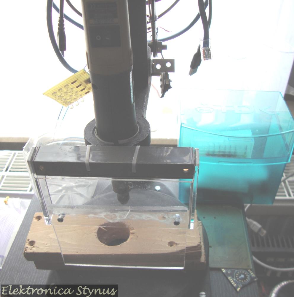
I am working on a drill press to drill my PCBs. For the standard I found and restored an old drill press. The drilling machine will be the one I already have in use. The speed will be controlled by an diy PWM speed controller. Circuit: http://www.circuitsonline.net/circuits/view/17
Pictures PWM controller:
Today I finished the restoration of the drill standard and I've mounted some leds on it:
On a sale I found a counter, and thought it would be nice to have that on my drill press to count the holes I drill. so I bought it and mounted it.
Pictures:
The counter: (Mounted with double sided tape)
The switch (Normally closed contact):
Circuit:
The led’s I used where poor quality and broke after some time. When I wanted to replace them I saw this post of vdbeke and decided to do something similar.
I used 3 pieces of pcb soldered together in a triangular form. In the side's I've mounted 3 led’s. This way I don't have the risk of drilling in the led’s.
Some time ago the motor from the drill had died. So I replaced it with the proxxon that I bought for my cnc machine.
A few weeks later the leds underneath died. I had some 3W leds + drivers in stock, so I decided to build a led driver and put a 3W led under the pcb.
Led driver:
Circuit drawing & pcb:
(External variable resistor = 100K)
Fixed to the board:
Led:
Test:
Date: 24 Mar 2011, 12:02
The diodes under the pcb are a very clever idea !
Date: 17 Aug 2011, 14:40
Indeed!!! The diodes under the pcb are a very clever idea !


