Category: Stopped/Failed projects

CNC drill/mill machine V2 – Mechanical Part – Update

I have received another set of bearing holders (Thanks Jaak!!). Yesterday I mounted 2 off them at the Y-axis and I made another nut from plastic. I also made a bracket from some scrap rvs to mount the stepper. The coupling with the spindle is made from a piece of scrap brass with some bolts.

koppelstuk

To protect the axis I’ve put some inductive end sensors on it, and on the back I’ve made a cable duct for the cables from the Z-axis.

vooraanzicht cnc

(Clickable)

achteraanzicht cnc

(Clickable)

CNC drill/mill machine V2 – Electronics Part – Update

I made another 2 stepper drivers:stappenmotorsturingen


Yesterday I made a new motherboard. The old 1 had a few design flaws in it. The new one is for 4 axis so I don’t need to build another one if a forth axis is added.

Circuit:

schema


Pcb:

pcb

PCB layout


Partlist:

Name:
Value:
R1, R2, R3, R4 4K7
R5, R6, R7, R8, R9, R10, R11, R12 470R
R13, R14, R15, R16 330R
R17, R18, R19, R20 3K3
C1 4700µF
C2, C3 100n
D1, D2, D3, D5 1N4004
IC1 ULN2803
IC2 7805
LED1, LED2, LED3, LED4,
LED5, LED6, LED7, LED8
LED groen 5mm
LED9, LED10, LED11n LED12 LED rood 5mm
OK1, OK2, OK3 PC849
TR1 Transformer 1.5VA 9-20V
X1 25p sub-d connector
X2, X3, X4, X5 3p printkroonsteentje
X6 5p printkroonsteentje
X10 2p printkroonsteentje 230V


mobo

mobo

CNC drill/mill machine V2 – Electronics Part – Update

I designed the pcb for the stepper driver. It uses an L297 and L298 ic. The circuit I used:

Schema Stappenmotor sturing cnc L297 L298

(Clickable)

Stappenmotor sturing pcb cnc L298 L297

(Clickable)


Partlist:

Name:
Value:
R1, R2, R3, R4 1R 3W
R5 100R 5W
R8, R9 10K
R10 25K trim potmeter
R11, R12 22K
C1 1000µF 50V
C2, C3, C4, C5, C6, C7, C8 100nF
C9 3,3nF
D1, D2, D3, D4, D5, D6, D7, D8 MUR440RL
IC1 7805
IC2 L297
IC3 L298
J1, J2 AMP vlakstekker
J4 3p pin header
X1 3p printkroonsteen
X2 5p printkroonsteen
X3 fan connector
F1 4A fuse + holder
M1 40mm 5V Fan (optional)


stappenmotor sturing

stappenmotor sturing

stappenmotor sturing

CNC drill/mill machine V2 – Mechanical Part – Update

I finished the Y-axis and made a bed from epoxy coated plywood.

vooraanzicht cnc

achteraanzicht cnc

I also reinforced the pillars.

250W Subwoofer Amplifier – Update

Today I made a pcb with capacitors. On the pcb I soldered 12 3300µF 100V capacitors. I bought these cheap on a radio flea market.

elco print

elco print

elco print

CNC drill/mill machine V2 – Electronics Part – Update

This week I have build the drivers in to the case.

sturingen ingebouwd


I also finished the front panel.

frontplaat cnc

Frontplaat cnc sturing


The backpanel is almost finished.

achterkant cnc sturing

On the right there are 3 connectors for the steppers missing. I still need to order those.

CNC drill/mill machine V2 – Electronics Part – Update

I bought a Proxxon micromot for the milling motor. The micromot doesn’t has a speed control build in, so I build one myself based on some recycled parts.

schema


Pictures:

Proxxon regeling

Proxxon regeling

The Proxxon:

proxxon micromot


The clamp I made for it:

proxxon klem


A video of the x-axis working:

I’ve got the Y axis working to but with the Z axis there is something wrong with the stepper.

CNC drill/mill machine V2 – Mechanical Part – Update

I have had a new Z-axis construction made (Thanks Jaak!). This needed to be done because the old one had 2mm of play on it. The new Z-axis is based on a compact cylinder.

Drawing:

Z-as tekening
(Clickable)


Z-as tekening
(Clickable)


Nieuwe Z as

Nieuwe Z as

Nieuwe Z as

Nieuwe Z as


Video of the Z-axis working:

CNC drill/mill machine V2 – Electronics Part – Update

The relays I used as “emergency stop” relays had some trouble with burned and sticky contacts. I replaced it with a bigger 40A relays but that also got the same problems (probably because of the inrush currents). Then I decided to make a solid-state relays with 4 TIP2955 transistors.


The circuit:

Schema SSR


To drive this solid state relays and provide 12V for the fan in the back of the case I made a 12V power supply. On the cnc there will be led lighting, and that is also powered by this power supply.


Circuit:

Sturing


print

The traces on the underside of the ssr are reinforced with wire so it can handle more current.

onderkant


I also painted the top of the case.

Deksel

Deksel

Symmetric Power Supply 0-70V @ 5A – Update

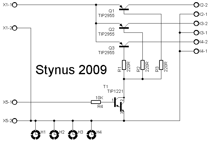
After a long time I restarted building on this power supply. I found a circuit where I’m going to base it on.

schema

I’m not going to use this circuit exactly, but the main part I do.

In this design they used TIP142 transistors. In my version I used MJ2955 transistors. I was doubting if I would change the design or change the transistors on the heat sink. After a lot of thinking I opted for the second option. The new transistors are mounted directly on the heat sink, where the old ones used an bracket. This should provide a better cooling.

Koelplaat

I didn’t trust the big capacitors I first planned to use any more. 1 of the 2 is so dehydrated that if you shake it you hear the inners rumbling louse. Instead of buying new big capacitors I opted to buy a few smaller ones. This is cheaper and gives a lower ESR. To mount them I made a pcb. Per side I use 3 capacitors of 3300µF 100V. That gives a capacity of 9900µF per side, this should be more than enough.

elcoprint

The next update will be the analog print. This design is 90% ready so it should not take too long (if no other project gets in between.)