Category: Projects

WMRP & WMRT Compatible Soldering Stations

Some time ago I bought a lot of Weller soldering irons at an auction for cheap. For the de-soldering iron I already made a station. In this lot were also a WMRT soldering tweezers cable. Next to that I bought a WMRP iron at a ham flea market. Only problem was that I do not have a station for these. I could buy one, but they are rather expensive.

After some searching for options I came across this site: http://kair.us/projects/weller/index.html I immediately ordered myself a set of boards to make a DIY one.

However I then came to the conclusion that I did not really like having 2 extra boxes on my desk for the stations. I want something that is small and hides somewhere. Maybe underneath the soldering iron stand. So I designed my own board and enclosure to 3d print. A few weeks later the boards came in.

The display and rotary encoder are now on a separate board that mounts at a right angle to the main board. On the back end of the board panel  is also a board to mount in the WMRT holder because I suspected it was broken. (Later on I found out it was still ok.)

3D Design:

For both the WMRT and WMRP this part was exactly the same.

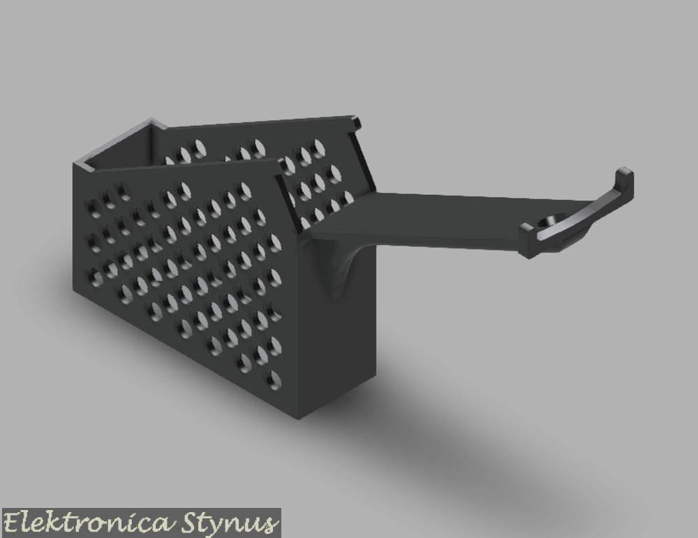
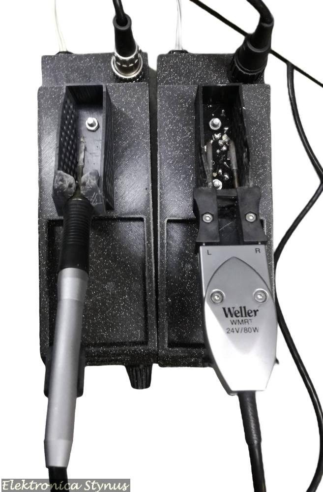
Next part was a holder for the iron. I could either build something out of metal or 3d print it. I chose for the second. The base was printed out of normal PLA since it does not really get hot unless a piece of molten solder falls on it. For the holder it is a different story. I needed a material that can handle high temperatures.  This was not easy to find, but I found out that objects made in the resin printer can handle the heat quite well if you do not force the tips into it. Therefore I chose to print these out of resin.

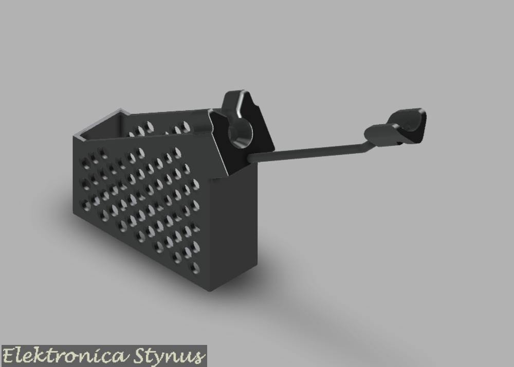
For the WMRT the complete thing is resin with a magnet pushed in. For the WMRP the main part is resin, but the long thin support I made from 6mm² copper wire.

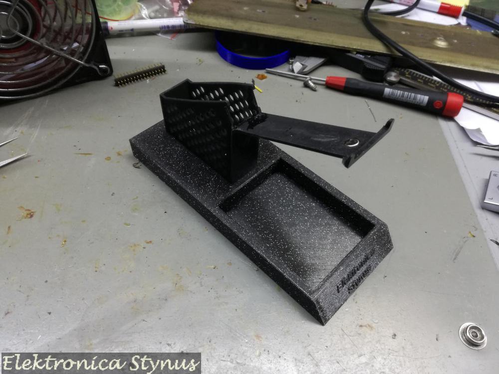
On the bottom of the iron bases I glued some washers. In the station part are some magnets, this makes that the base does not move easy on the station part, but can be detached when needed.

Next I needed a way to connect them to the 12V desk PSU. I also wanted a way to switch them on / off. So another box with switches needed to be build.

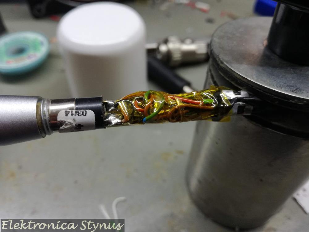
Ok, so now the WMRT works, but the WMRP I found out was not a WMRP but a WXMP. This means that the reed switch is replaced by a hall sensor and a lot of electronics are added. I removed this board and replaced it by a piece of experiment board with a reed switch from a door contact and the KTY 82 temperature compensation.

Now my desk looked like this: 

As you can see the front of the stations is still open, so this was the next project. For this I used some black mirror transparent plexi. The button was 3D printed.

Off:

On:


Files / Links:

Solder / SMD Inspection Camera

For some time I wanted an camera to inspect solder joints / SMD parts.

What I wanted it to have was:

  • +-30x zoom.
  • Automatic focus with an option to manual focus.
  • Ability to make pictures.
  • Polarised filter.
  • Camera on an arm so it can be pulled over the PCB and pushed back when not in use.
  • Not one of those cheap cameras with build on much too small screen.
  • Connection to the PC, preferred display on the PC screen.

I found a few options, but they ware either too expensive, or the quality too low. Some time went by and then I came across a camera module at a HAM flea market. This one was not too expensive, but was only a camera module that was open on all sides. Therefore the first job was to design an enclosure. I was inspired by a professional version:

The enclosure I 3D printed in PLA. For the rails I used some old printer guide rails with slide bearings on them.

The left picture is when the camera is not in use. It is pushed completely to the back and the slides are locked in place with a magnet. The other 2 pictures are when it is slide out and in use.

Inside the enclosure it looks like this:

It contains a PCB that receives bus signals, drives the LED ring and forwards messages that are meant for the camera.  For the connection of the camera to the PC, it contains a 4ch composite to USB converter (I had this one and did not want to order an extra 1ch version).

The cable that exits the camera enclosure connects to a controller.

With this controller box I can set the zoom level, focus level, intensity of the LEDs and the iris.

In the back panel is a USB plug, this one is connected to the composite to USB converter in the camera. The other input is a 12V power adapter and a programming plug for if I need to make a firmware update.
For the cable between this camera enclosure and the controller used a USB3 cable with the ends cut off. This way I have the 4 usb2 wires and an extra 4 wires for signals and power.


Underneath the camera I made a LED rind to illuminate the area.  Under that I made a polarising filter.

With this filter I can change the polarisation angle of the LED ring with respect to the angle of the filter on the camera lens by rotating the polarisation ring. This makes it possible to make text on IC’s visible that would normally be hard to see. For example, below is one picture with the filter at a random angle and then rotated to a good visibility:


More details on the PCB’s:

The LED ring / camera controller board:

Controller Board / 28pin PIC breakout board:

Lab power supply 0-24V 0-2A DC

I’m finishing some old projects. One of these project is a lab powersupply based arround a kit I bought on AliExpress.

I had a old transformer from a crt screen that outputs 22V at enough power (does not get hot at full load) and as a bonus has shielding on the outside. For the enclosure I used an enclosure of a 230->110V transformer that I got very cheap at an auction some time ago. The front and back panel are 3D printed

The heatsink I used is from a I5 pc. The fan is a 12V fan that makes too much noise. Thats why I put a 5V regulator in series, that regulator is also mounted on the heatsink because it will get hot. The fan is switched with a clixon contact near the transistor.

When the enclosure is closed, the power supply looks like this:

Pioneer IR Remote

I have a Pioneer XR-A550 hifi system that I use as an amplifier for sound / music from my pc. This works great, however at the end of the day I switch the power of my bench off, this includes the Pioneer.  When I switch on the power again the Pioneer has lost all its settings, so I have to enter it in aux mode and turn the volume back up. After doing this for a few years it was time to automate this.

To do this I decided to replicate the IR remote commands with my own circuit. For the board I used a spare board from my Solder / SMD inspection Camera project, this board has a microcontroller and a mosfet to drive a higher current load. So it makes it ideal to drive the IR LED.

The enclosure is 3D printed and is designed to clip onto the aluminium of my LED light.

To get the IR commands I connected a IR receiver to a logic analyser. The signals I then decoded in a spreadsheet and made some quick and dirty code to reproduce them.

The signal for the  IR LED needs to be modulated at 38Khz, for this I used a PWM module in the microcontroller. I send duty-cycle 0 for off and 50% for on. LATAbits.LATA6 I used for debug to compare the signal to the original. This results in folowing code:


void main(void)
{
    uint8_t Buffer, Counter, VolumeCounter;
    // initialize the device
    SYSTEM_Initialize();   
    
    //**************************************************************************
    //Startup delay    
        __delay_ms(2000); 
        __delay_ms(2000); 
      
    //**************************************************************************
    //Send Aux
        Irheader();

        Buffer = 0b10011010;
        for (Counter = 0; Counter < 8; Counter++)
        {
            if (Buffer & 0x80){
                IrOne();
            }else{
                IrZero();
            }
            Buffer = Buffer << 1;
        }

        Buffer = 0b01100101;
        for (Counter = 0; Counter < 8; Counter++)
        {
            if (Buffer & 0x80){
                IrOne();
            }else{
                IrZero();
            }
            Buffer = Buffer << 1;
        }

        Buffer = 0b11001101;
        for (Counter = 0; Counter < 8; Counter++)
        {
            if (Buffer & 0x80){
                IrOne();
            }else{
                IrZero();
            }
            Buffer = Buffer << 1;
        }

        Buffer = 0b00110010;
        for (Counter = 0; Counter < 8; Counter++)
        {
            if (Buffer & 0x80){
                IrOne();
            }else{
                IrZero();
            }
            Buffer = Buffer << 1;
        } 
        IrZero();
    
    //**************************************************************************
    //Delay after power on
        __delay_ms(2000); 
        __delay_ms(2000); 
     
    //**************************************************************************  
     //Volume ++ 10x 
        for (VolumeCounter = 0; VolumeCounter < 10; VolumeCounter++){
            Irheader();

            Buffer = 0b10011010;
            for (Counter = 0; Counter < 8; Counter++)
            {
                if (Buffer & 0x80){
                    IrOne();
                }else{
                    IrZero();
                }
                Buffer = Buffer << 1;
            }

            Buffer = 0b01100101;
            for (Counter = 0; Counter < 8; Counter++)
            {
                if (Buffer & 0x80){
                    IrOne();
                }else{
                    IrZero();
                }
                Buffer = Buffer << 1;
            }

            Buffer = 0b10101111;
            for (Counter = 0; Counter < 8; Counter++)
            {
                if (Buffer & 0x80){
                    IrOne();
                }else{
                    IrZero();
                }
                Buffer = Buffer << 1;
            }

            Buffer = 0b01010000;
            for (Counter = 0; Counter < 8; Counter++)
            {
                if (Buffer & 0x80){
                    IrOne();
                }else{
                    IrZero();
                }
                Buffer = Buffer << 1;
            } 
            IrZero();
             __delay_ms(1000); 
        }

    //**************************************************************************  
    //Infinite loop, don't do anything
    while (1)
    {        
    }
}

void Irheader(void){
    LATAbits.LATA6 = 0;  
    PWM1_LoadDutyValue(127);
     __delay_us(8550); 
    LATAbits.LATA6 = 1;   
    PWM1_LoadDutyValue(0);
     __delay_us(4200);     
}
void IrOne(void){
    LATAbits.LATA6 = 0;   
    PWM1_LoadDutyValue(127);
     __delay_us(550); 
    LATAbits.LATA6 = 1;   
    PWM1_LoadDutyValue(0);
     __delay_us(550);     
}
void IrZero(void){
    LATAbits.LATA6 = 0;   
    PWM1_LoadDutyValue(127);
     __delay_us(550); 
    LATAbits.LATA6 = 1; 
    PWM1_LoadDutyValue(0);
     __delay_us(1560);     
}

A video of the circuit working:

Please accept YouTube cookies to play this video. By accepting you will be accessing content from YouTube, a service provided by an external third party.

YouTube privacy policy

If you accept this notice, your choice will be saved and the page will refresh.


Related products:


Spare sensor set

Weller TCPS Power Supply

For a TCPS soldering iron that was in a auction some time ago I wanted to make a power supply. In my parts collection I had a spare Weller transformer that was perfect for this. For the enclosure I used an enclosure of a 230->110V transformer that I also got very cheap at an auction some time ago. The front panel is 3D printed. To store the soldering iron and the tips I also 3D printed a drawer that is mounted underneath the power supply.


Dual Lab Power Supply 0-48V 0-3A DC

Although having made more than enough power supply’s, there where still some boards in my storage that I bought from a fund raiser at Circuits Online. These are a dual 0-34V 2,5A PSU with tracking. It would be a waste to have the boards and not build them.

(Above pictures are from CircuitsOnline because I forgot to take pictures myself)

As with the previous PSU build kit (Lab Power Supply 0-70V 0-3A) I was not completely happy with the specs (/wanted to make it more of a challenge) and decided to change them to 2x 0-48V 0-3A. This would mean the transistors had to dissipate a lot more heat. To counter this I used a switch mode power supply instead of a normal transformer. This switch mode power supply I modded so It can be controlled by a 0-1.5mA signal to give 20-60V on the output. This way the voltage on the transistors is limited to 20V max. I made a circuit to keep te input voltage about 10V higher then the output voltage.
This circuit I build using 1 of the op-amps on the main board and a small piece of pcb added fixed to a unused connector.

After this the power supply needs to  be changed. Some components can not handle the larger voltage, some resistors need to be adjusted to increase the range and some other modifications have to be done.

Now that the PSU works, it was time to make an enclosure. I could not really find what I was searching for, so I decided to 3D print the entire enclosure. This way it is exactly to size and I can add custom features, like  the front is on a big printed hinge, making it easier to work / measure on the boards.

On the bottom are 3 power supply’s (2x modded 48V SMPS, 1x 12V for the fans), 4x 12V transformer for auxiliary voltages of the supply circuits.

Above this level are the heat sinks, for this I used old processor coolers, where the transistors are clamped on with a  metal sheet. The fans on these heat sinks can be PWM controlled, so I used a simple dev board (the blue one in the centre) to read out 2 temperature sensors and drive 2 fans.

In the front are the 2 lab PSU boards, and on the front panel the display/pot PCB’s:

The end result:

On the equipment shelve:

Wire Twisting Machine

I needed a lot of twisted wire and I could not find it anywhere in the correct thickness / colour.  I could have it custom made, but this would be too expensive. I could hand twist it with a drill, but that would limit it to 10 meter at a time. So I decided to make a machine to twist wire.

At this time I got a motor, belt and bearing assembly from a washing machine. This makes a good base to build something on. I mounted the assembly on a wooden board and made a round disk on the tub mount.

Next I mounted 2 spool holders on the disk, they use a M12 al-tread axle with 2 conical clamps. At first I used bearings to make it easier for the spools to turn, but after some experiments it turned out it needed some resistance, so I replaced them with 3D printed blocks. Above the spools I made a funnel to make the wire always exit in the same spot.

Next I made a spool winder with a gearbox motor:

Next I made an arm above the machine to guide the wire:

To control the 2 motors I used 2 motor controllers and a DC power supply for the 12V motor. These I build into a box:

DC:

AC:

I have written a small tutorial on how to drive a washing machine motor with this controller:  Link

The machine in action:

Please accept YouTube cookies to play this video. By accepting you will be accessing content from YouTube, a service provided by an external third party.

YouTube privacy policy

If you accept this notice, your choice will be saved and the page will refresh.

Spotwelder

I picked up this project from a few years ago again. First I connected the cap pcb on 5V, but it immediately started to pull a lot of current. 1 of the caps was shorted internally. With a lot of effort I found which one it was and replaced it. The I powered the circuit again, did a test weld and did not have a lot of power (almost no current even).

After a few test I had to replace another 2 capacitors that had shorted internally. And a few minutes later the board had a shorted cap again. Now I ran out of spare caps, and I had to decide if I wanted to order new ones. I decided to first calculate the energy that could be stored in the caps and also found out that it was not enough. After some searching on the internet I came across some high capacity capacitors, but they were expensive.

Then I remembered I have a few microwave oven transformers laying around and decided to use one of those. The HV secondary I removed and replaced with some 16mm² wire. The primary I switch with a solid state relay. To control everything I used a small board with a PIC16F1788 microcontroller. On this I put a ULN2803 board to drive the solid-state relays, a buzzer, LCD and a rotary encoder.

Now for detecting when to weld. On the old circuit I just used a pull-up resistor and measured the voltages on the pins. With the new version this can not be done since to 16mm² wire is always low resistance. The way I solved this is by injecting a 50Khz wave onto the wires and measure how much it drops when the pins are shorted. The thick wire on the transformer forms an inductor and is like a open circuit for the 50Khz.
In order to put the signal on to the wire I need more power then the standard pin can deliver, therefore I used a RS485 transceiver as an amplifier. After the RS485 IC is a 1µF capacitor to couple the signal.

I first did a simulation and got this result (left on the plot is output open, right is switch closed to simulate the welding pins to metal).

The out signal of this schematic is connected to an AD converter in the microcontroller. When the signal is below a threshold the welding program starts. The program I made so that it can do 2 pulses. The pulse time of both pulses and the pause time can all be set individually.


The main part of the program:

 while (1)
    {   
        
        MenuDelay ++;   //For debounce
        if (MenuDelay > 4){
            MenuDelay = 0;
            
            if (WeldState){
                LCD_Print_At(1, 1, "Stat:Weld|T1PaT2"); 
            }else{
                LCD_Print_At(1, 1, "Stat:Open|T1PaT2");                 
            }    
            
            sprintf(GetString,"%4u", WeldTime1 * 20); 
            LCD_Print_At(2, 1, GetString);  
            sprintf(GetString,"%4u", WeldPause * 20); 
            LCD_Print_At(2, 6, GetString);      
            sprintf(GetString,"%4u", WeldTime2 * 20); 
            LCD_Print_At(2, 11, GetString);     
            LCD_Print_At(2, 5,  "|");
            LCD_Print_At(2, 10, "|");    
            LCD_Print_At(2, 15, "mS");  
            
            LCD_Cmd(0xFE);
            LCD_Cmd(0x0E);
            LCD_Cmd(0x0F);
            
            switch (MenuItem){ 
                case 0:     
                    LCD_Goto(4, 2);                      
                    WeldTime1 = RotCountValue;
                    if (!RotaryBtn){
                        DATAEE_WriteByte(1, WeldTime1); 
                        MenuItem ++;
                    }
                    break;  
                case 1:
                    if (RotaryBtn){
                        MenuItem ++;
                        RotCountValue = WeldPause;
                        RotMinValue = 1;
                        RotMaxValue = 100;
                        LCD_Cmd(LCD_CLEAR);   
                    }
                    break; 
                case 2:     
                    LCD_Goto(9, 2);  
                    WeldPause = RotCountValue;    
                    if (!RotaryBtn){
                        DATAEE_WriteByte(2, WeldPause); 
                        MenuItem ++;
                    }
                    break; 
                case 3:
                    if (RotaryBtn){
                        MenuItem ++;
                        RotCountValue = WeldTime2;
                        RotMinValue = 1;
                        RotMaxValue = 100;
                        LCD_Cmd(LCD_CLEAR);   
                    }
                    break;                    
                case 4:     
                    LCD_Goto(14, 2);                     
                    WeldTime2 = RotCountValue;
                    if (!RotaryBtn){
                        DATAEE_WriteByte(3, WeldTime2); 
                        MenuItem ++;
                    }                    
                    break;  
                default:
                    if (RotaryBtn){
                        MenuItem = 0;
                        RotCountValue = WeldTime1;
                        RotMinValue = 1;
                        RotMaxValue = 100;
                    }
                    break;
            }      
        }
        
        SensVoltageBuffer = 0;
        for (uint8_t Counter = 0; Counter < 6; Counter++){ 
            SensVoltage = ADC_GetConversion(0); SensVoltage = SensVoltage >> 6;
            SensVoltageBuffer = SensVoltageBuffer + SensVoltage;      
            __delay_ms(20/6);        
        }
        SensVoltage = SensVoltageBuffer / 6;
        WeldDetect = 200;    
        
        switch (WeldState){
            case 0:
                if (SensVoltage < WeldDetect){
                    WeldState ++;
                }
                break;
            case 1:            
                WeldState ++; 
                WeldTimer = 0;
                break;
            case 2:
                if (SensVoltage < WeldDetect){ 
                    WeldState ++; 
                }else{ 
                    WeldTimer ++; 
                    if (WeldTimer == 250){ 
                       WeldState = 0; 
                    } 
                } 
                break; 
            case 3: 
                LATBbits.LATB4 = 1; //Buzzer 
                WeldState ++; 
                break; 
            case 4: 
                LATBbits.LATB4 = 0; 
                WeldState ++; 
                break; 
            case 5:
                WeldTimer = 0; 
                WeldState ++; 
               break; 
            case 6: 
               LATAbits.LATA3 = 1; 
               LATBbits.LATB5 = 1; 
               if (WeldTimer >= WeldTime1){
                    LATAbits.LATA3 = 0;
                    LATBbits.LATB5 =0;
                    WeldTimer = 0;
                    WeldState ++;
                }else{
                    WeldTimer ++;
                }
                break;
            case 7:
                if (WeldPulses == 1){
                   WeldState = 10; 
                }
                if (WeldTimer >= WeldPause){
                    WeldTimer = 0;
                    WeldState ++;
                }else{
                    WeldTimer ++;
                }
                break;
            case 8:
                LATAbits.LATA3 = 1;
                LATBbits.LATB5 = 1;
                if (WeldTimer >= WeldTime2){
                    LATAbits.LATA3 = 0;
                    LATBbits.LATB5 = 0;
                    WeldTimer = 0;
                    WeldState ++;
                }else{
                    WeldTimer ++;
                }
                break;
            case 9:
                WeldState ++;                
                break;               
            case 10:
                WeldTimer ++;
                if (WeldTimer >= (1000/20)){
                    WeldTimer = 0;
                    WeldState ++;
                }
                break;   
            case 11:     
                 if (SensVoltage > WeldDetect){
                    LATAbits.LATA3 = 0;
                    WeldTimer = 0;
                    WeldState = 0;
                }      
                break;                     
            default:
                WeldState = 0;
                break;                    
        }   
    }


Water Dispenser

During my home renovation, I found myself wasting a lot of time measuring water for mixing concrete, gypsum, and other materials. To streamline the process, I built this automatic water dispenser. It allows precise dispensing from 0.1L to 25L in 0.1L increments. The last set value is stored in memory and retained even after a power cycle.

Pictures of the finished project:

Please accept YouTube cookies to play this video. By accepting you will be accessing content from YouTube, a service provided by an external third party.

YouTube privacy policy

If you accept this notice, your choice will be saved and the page will refresh.

The unit runs on a rechargeable lithium battery, which is charged by a water-powered generator. This means the battery charges while water is being dispensed. In the rare case the battery runs out (unlikely, as the charging power exceeds the average consumption), there’s a USB-C charging port hidden behind a screw-in plug on the side.

The solenoid valve I used is pulse-driven: a single pulse opens the valve, and a reverse pulse closes it. This design significantly reduces power usage. To drive the valve, I use a compact MX1508 motor driver board. However, the current spike during valve switching can cause the microcontroller to crash. To avoid this, I added a buffer circuit consisting of 3x 3300µF 6.3V capacitors charged through a 100Ω resistor from the 5V line. This buffer powers only the valve driver, isolating it from the main 5V supply and preventing voltage dips during switching.

The water flow is monitored using a flow sensor that generates 660 pulses per liter. These pulses are fed into a microcontroller pin configured to trigger an interrupt. Each interrupt decrements a remaining volume counter, and once the counter reaches zero, the valve is closed.

A quick sketch circuit diagram:

The firmware can be found on Codeberg: https://codeberg.org/Stynus/Water-Dispenser