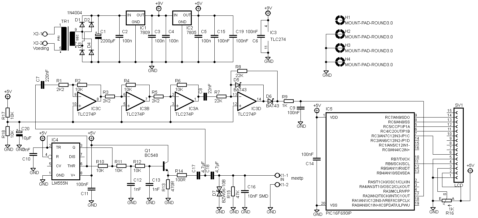
There was another adaptation on the pcb that was not in the circuit diagram above.

The LCD has to be connected differently. I don’t know why anymore, but here is the new circuit diagram:
I received Eagle files from Predrag Mihajlovic for this esr meter. They can be downloaded here: Link.
Hello,
I did 2 versions. First is one based on your schematics, except that I’ve changed those smd capacitors for standard through hole ones. Second one is somewhat modified. I’ve excluded transformer and put in standard dc jack. Also, pic and display header are located so far away from other stuff so that there is enough place for display to be on the pcb. Also, you’ll see that, on both versions I’ve also put pads for 27 and 22mm capacitors (4.7uF). Check it out and feel free to make any modifications you think are necessary. You can put it on your website if you like, maybe someone will find it useful 🙂
Peca.
4 comments
Skip to comment form
hi, is the hex code available for this project?
Author
Hello,
Yes, it is in the previous update: https://en.elektronicastynus.be/2009/02/24/esr-meter-update-2/
Complete project overview: https://en.elektronicastynus.be/category/projects/measuring-equipment/esr-meter/
Regards,
Stijn
HELLO, I AM HAVING DIFFICULTY DOWNLOADING THE FILES
Author
Hello,
There was an old link extra in the post, I removed it. The download link for Predrags files works. My files can not be downloaded since they are far from complete with all the reworks afterword.
Regards,
Stijn