Category: UV-Exposure box V3

UV-Exposure box V3

If I had to expose a double sided PCB with my previous exposure box, I needed to turn it on twice. (1 time for the top, and 1 time for the bottom) To solve this problem it was time to build a new version. This new version will do the 2 side’s at once.


This time I chose for LED’s instead of fluorescent light, so I designed some PCB’s to mount the leds on to. The PCB’s will be connected per 6. This allows me to exposure PCB’s off 20 * 30cm max. The top of the board has no solder mask. This works as a reflector.

http://image.elektronicastynus.be/81/1311520153.jpg

Soldered:

http://image.elektronicastynus.be/81/1311520176.jpg

Test:

http://image.elektronicastynus.be/81/1311520160.jpg


Then came the biggest work: The case make. To save space I didn’t use the traditional flap open model but a kind of sliding model. Where the glass panels slide out.

http://image.elektronicastynus.be/81/1311520158.jpg

You can pull the upper plate up to insert the pcb between the glass sheets and to clamp it.

The base plate with spacers and two side plates::

http://image.elektronicastynus.be/81/1311520170.jpg


With the slider mounted:

http://image.elektronicastynus.be/81/1311520167.jpg

http://image.elektronicastynus.be/81/1311520161.jpg

Test with glass in it:

http://image.elektronicastynus.be/81/1311520182.jpg


I added some springs on the screws to make the hinges clamp the glass

http://image.elektronicastynus.be/81/1311522816.jpg

On the front I added some bulletsnaplocks.

http://image.elektronicastynus.be/81/1311627001.jpg

The top plate mounted with the buttons / LCD on the place where they should be mounted.

http://image.elektronicastynus.be/81/1311520164.jpg

For the power supply I used a 20V toroidal transformers. The voltage is a bit high, so I used some switching voltage regulators to power the led pcb’s.

http://image.elektronicastynus.be/81/UV_PSU.png http://image.elektronicastynus.be/81/UV_PSU_PCB.png

http://image.elektronicastynus.be/81/1311626823.jpg

(One of the voltage regulators is still on order.)

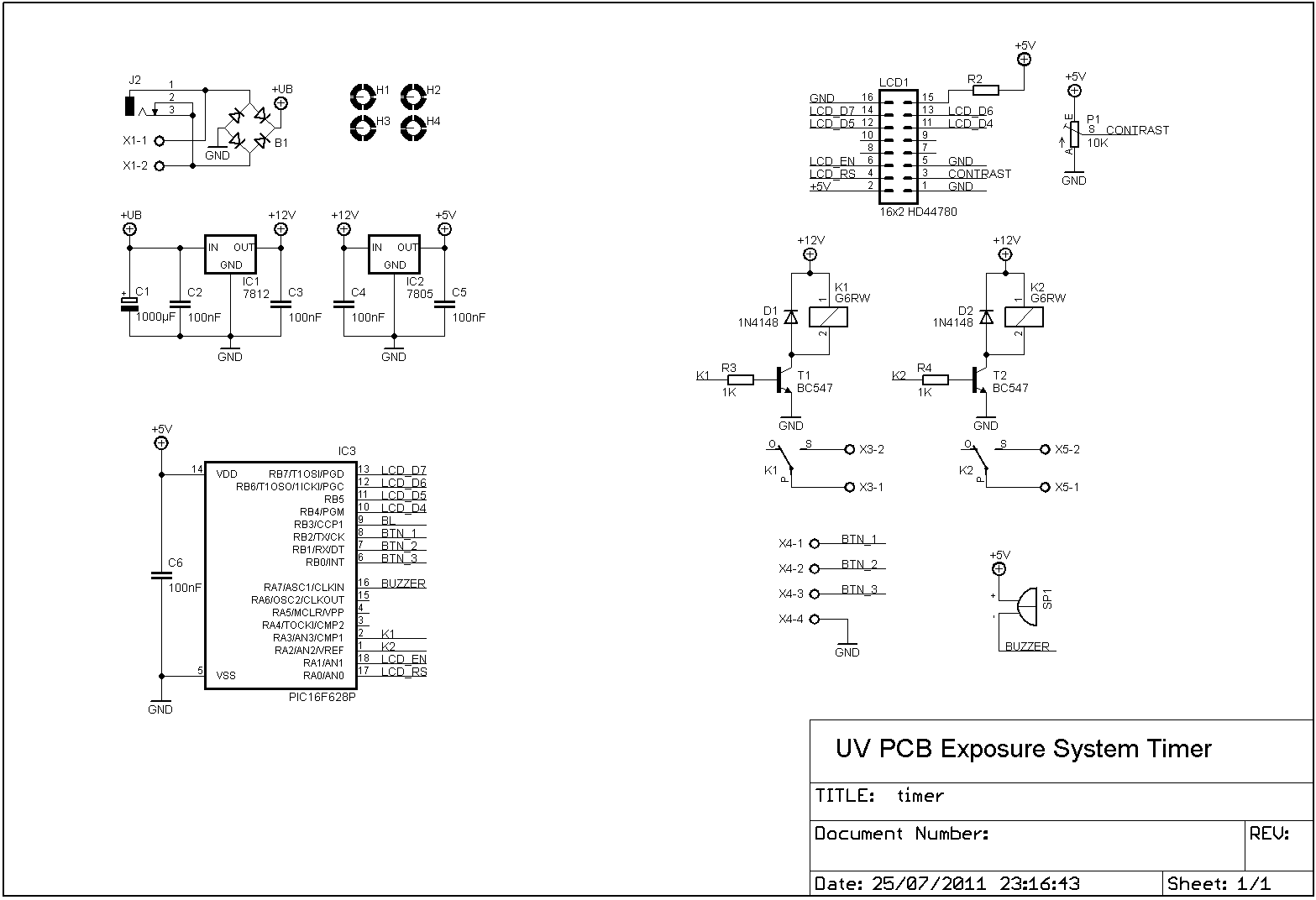
I made a new timer to switch the light panels. This new timer remembers the last exposure time, so you don’t have to remember it yourself anymore..

http://image.elektronicastynus.be/81/UV_Timer.png http://image.elektronicastynus.be/81/UV_Timer_PCB.png

http://image.elektronicastynus.be/81/1311626820.jpg

Build in the case:

http://image.elektronicastynus.be/81/1311626826.jpg

UV-Exposure box V3 – Update

The project is finished now.

Some pictures from during the build:

Spray painted the sides + bended a top cover plate.

http://image.elektronicastynus.be/81/1313516075.jpg

http://image.elektronicastynus.be/81/1313516087.jpg

Mounted the front plate:

http://image.elektronicastynus.be/81/1313516080.jpg

Inside:

http://image.elektronicastynus.be/81/1313516083.jpg


Finished:

http://image.elektronicastynus.be/81/1313409198.jpg

http://image.elektronicastynus.be/81/1313409216.jpg


Placed on the location of the old exposure box:

http://image.elektronicastynus.be/81/1313516073.jpg

http://image.elektronicastynus.be/81/1313516082.jpg

With the slide out:

http://image.elektronicastynus.be/81/1313516781.jpg

Open:

http://image.elektronicastynus.be/81/1313516787.jpg

Clamped PCB:


http://image.elektronicastynus.be/81/1313516784.jpg

Files

PCB files LED panels: Download

PCB files timer: Download

PCB files power supply: Download

Code timer: View / Download.

Available Products: