I was thinking about making a resistor decade box, but I found the rotary switches that are used in these most of the time rather expensive and a bit old fashioned. That’s why I decided to use a rotary encoder and select the resistors with a microcontroller.
Now I only had to find a way to “make” the resistance. Switching resistors with transistors or mosfets gives a high switch resistance and can’t handle AC voltages. That’s why I opted to use relays. The currents that need to be switched are rather small, therefore a small relay is sufficient. The relay board is used 2 times with different resistor values.
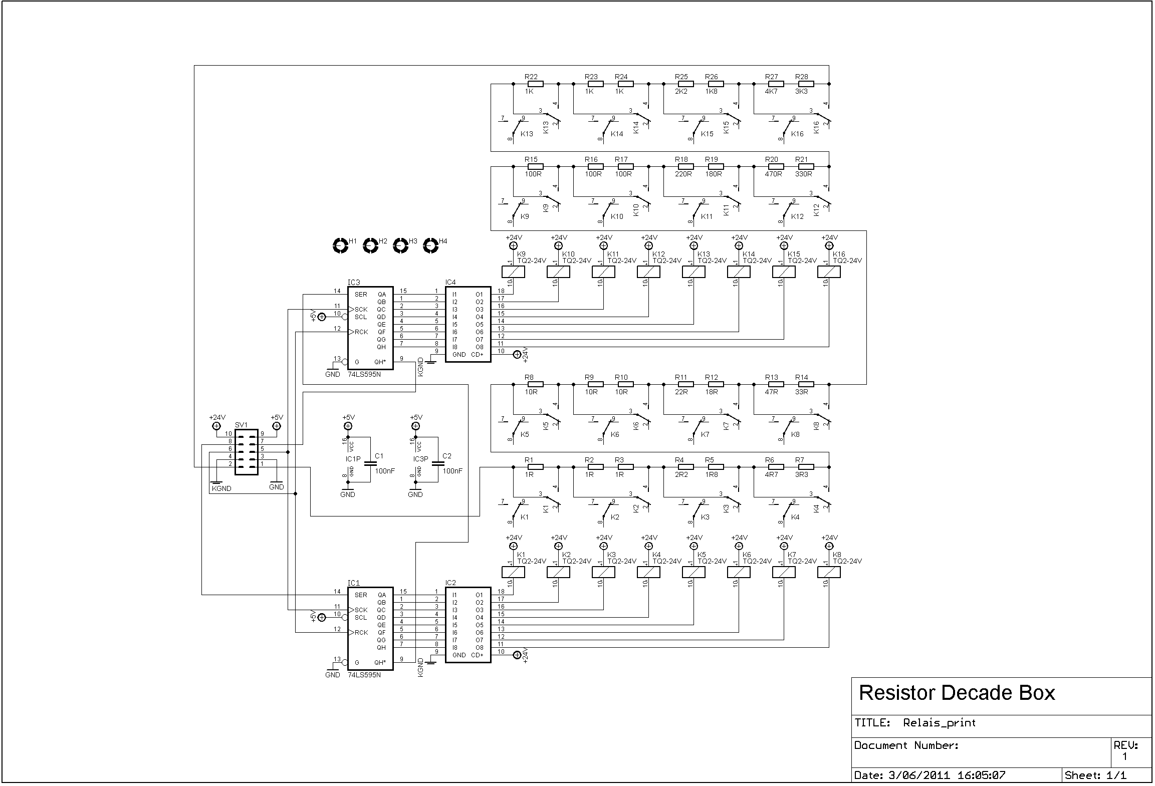
Relay PCB:


Part list:
PCB low resistance:
| 3 | 1K | R22, R23, R24 |
| 1 | 1K8 | R26 |
| 3 | 1R | R1, R2, R3 |
| 1 | 1R8 | R5 |
| 1 | 2K2 | R25 |
| 1 | 2R2 | R4 |
| 1 | 3K3 | R28 |
| 1 | 3R3 | R7 |
| 1 | 4K7 | R27 |
| 1 | 4R7 | R6 |
| 3 | 10R | R8, R9, R10 |
| 1 | 18R | R12 |
| 1 | 22R | R11 |
| 1 | 33R | R14 |
| 1 | 47R | R13 |
| 3 | 100R | R15, R16, R17 |
| 1 | 180R | R19 |
| 1 | 220R | R18 |
| 1 | 330R | R21 |
| 1 | 470R | R20 |
| 2 | 100nF | C1, C2 |
| 2 | 74HCT595 | IC1, IC3 |
| 2 | ULN2803 | IC2, IC4 |
| 16 | TQ2-24V | K1, K2, K3, K4, K5, K6, K7, K8, K9, K10, K11, K12, K13, K14, K15, K16 |
PCB high resistance:
| 3 | 10K | R1, R2, R3 |
| 1 | 18K | R5 |
| 1 | 22K | R4 |
| 1 | 33K | R7 |
| 1 | 47K | R6 |
| 3 | 100K | R8, R9, R10 |
| 1 | 180K | R12 |
| 1 | 220K | R11 |
| 1 | 330K | R14 |
| 1 | 470K | R13 |
| 3 | 1M | R15, R16, R17 |
| 1 | 1M8 | R19 |
| 1 | 2M2 | R18 |
| 1 | 3M3 | R21 |
| 1 | 4M7 | R20 |
| 2 | 100nF | C1, C2 |
| 2 | 74HCT595 | IC1, IC3 |
| 2 | ULN2803 | IC2, IC4 |
| 12 | TQ2-24V | K1, K2, K3, K4, K5, K6, K7, K8, K9, K10, K11, K12 |
Control PCB:


Part list:
| 2 | 1uF | C3, C4 |
| 1 | 10K | R2 |
| 1 | 10K | R1 |
| 1 | 16F648A (Programmed) | IC1 |
| 2 | 100nF | C1, C2 |
| 1 | Push button | S1 |
| 1 | Rotary encoder | S1 |
| 1 | REG1117-5V | IC2 |
With frontpanel:

Power supply
This part is made on experiment board, therefore there are no circuit drawings available. The pcb exists of a 18V transformer; a rectifier and a capacitor.
Everything mounted in the enclosure:

Ready:

Code in the microcontroller:
Device = 16F648A
Config FOSC_INTOSCIO, WDTE_OFF, PWRTE_ON, MCLRE_OFF, BOREN_OFF, LVP_OFF, CPD_OFF, CP_OFF

All_Digital           = true
Xtal                  = 4

Declare PortB_Pullups   On

Declare LCD_DTPin       PORTB.4
Declare LCD_ENPin       PORTB.2
Declare LCD_RSPin       PORTB.3
Declare LCD_Interface   4
Declare LCD_Lines       2

Symbol  RotEncoderA   = PORTB.1
Symbol  RotEncoderB   = PORTB.0
Symbol  RotSwitch     = PORTA.2

Symbol  PushSwitch    = PORTA.4
Dim     PushSwitchBit As Bit

TRISB                 = %00000011
TRISA                 = %01111100

OPTION_REG            = %01000000
INTCON                = %10010000
Symbol  INTF          = INTCON.1

Symbol  klok          = PORTA.0
Symbol  Data_Pin      = PORTA.7
Symbol  ZetVast       = PORTA.1

Dim  DispWaarde[7]    As Byte
Dim  SetWaarde[7]     As Byte
Dim  DispTeller       As Byte
Dim  CursorTeller     As Byte
Dim  UitHex           As Byte
Dim  UitDig           As Byte
Dim  UitCount         As Byte
Dim  ArrayTeller      As Byte
Dim  Warning          As Bit
'dim teller as byte

On_Hardware_Interrupt GoTo IrInterrupt

GoTo Init
'****************************************************************
IrInterrupt:
    Context Save
       If INTF = 1 Then
          'Flaggen resetten
          INTF = 0
          If RotEncoderA = 1 Then
             'Aftellen
             If DispWaarde[6 - DispTeller] > 0 Then
                Dec DispWaarde[6 - DispTeller]
             EndIf
          Else
             'Optellen
             If DispWaarde[6 - DispTeller] < 9 Then
                Inc DispWaarde[6 - DispTeller]
             EndIf
          EndIf
       EndIf
    Context Restore
'****************************************************************
Init:
    Cls

    UitDig = DispWaarde[3]
    UitHex = UitDig << 4
    UitDig = DispWaarde[2]
    UitHex = UitHex + UitDig
    UitHex = ~UitHex
    SHOut Data_Pin, klok, MsbFirst, [UitHex \ 8]

    UitDig = DispWaarde[1]
    UitHex = UitDig << 4
    UitDig = DispWaarde[0]
    UitHex = UitHex + UitDig
    UitHex = ~UitHex
    SHOut Data_Pin, klok, MsbFirst, [UitHex \ 8]

    UitHex = 0
    UitDig = DispWaarde[6]
    UitHex = UitHex + UitDig
    UitHex = ~UitHex
    SHOut Data_Pin, klok, MsbFirst, [UitHex \ 8]

    UitDig = DispWaarde[5]
    UitHex = UitDig << 4
    UitDig = DispWaarde[4]
    UitHex = UitHex + UitDig
    UitHex = ~UitHex
    SHOut Data_Pin, klok, MsbFirst, [UitHex \ 8]

    High ZetVast
    DelayUS 20
    Low ZetVast
                   '12345678
    Print At 1, 1, "E-Stynus"
    Print At 2, 1, "  2014  "
    DelayMS 750
    Cls

    Print At 1,1, "Set:"
    DispTeller = 0

    'Ohm teken in lcd steken
    Print $FE,$40,$00,$0E,$11,$11,$11,$0A,$1B,$00
'****************************************************************
Main:
While 1 = 1
   'Relais aansturen bij rotary encoder button druk
   If RotSwitch = 0 Then
      For ArrayTeller = 0 To 6
          SetWaarde[ArrayTeller]     = DispWaarde[ArrayTeller]
          If SetWaarde[ArrayTeller]  > 9 Then
             SetWaarde[ArrayTeller]  = 0
             DispWaarde[ArrayTeller] = 0
          EndIf
      Next

      UitDig = DispWaarde[3]
      UitHex = UitDig << 4
      UitDig = DispWaarde[2]
      UitHex = UitHex + UitDig
      UitHex = ~UitHex
      SHOut Data_Pin, klok, MsbFirst, [UitHex \ 8]

      UitDig = DispWaarde[1]
      UitHex = UitDig << 4
      UitDig = DispWaarde[0]
      UitHex = UitHex + UitDig
      UitHex = ~UitHex
      SHOut Data_Pin, klok, MsbFirst, [UitHex \ 8]

      UitHex = 0
      UitDig = DispWaarde[6]
      UitHex = UitHex + UitDig
      UitHex = ~UitHex
      SHOut Data_Pin, klok, MsbFirst, [UitHex \ 8]

      UitDig = DispWaarde[5]
      UitHex = UitDig << 4
      UitDig = DispWaarde[4]
      UitHex = UitHex + UitDig
      UitHex = ~UitHex
      SHOut Data_Pin, klok, MsbFirst, [UitHex \ 8]

      High ZetVast
      DelayUS 20
      Low ZetVast

      DelayMS 100
      While RotSwitch = 0
            DelayMS 100
      Wend

   EndIf

   'Warning teken
   Warning = 0
   For ArrayTeller = 0 To 6
       If DispWaarde[ArrayTeller] <> SetWaarde[ArrayTeller] Then
          Warning = 1
       EndIf
   Next
   If Warning = 1 Then
      Print At 1, 8, "!"
   Else
      Print At 1, 8, " "
   EndIf

   'Decade positie
   If PushSwitch = 0 And PushSwitchBit = 0 Then
      PushSwitchBit = 1
      DelayMS 100
      If DispTeller < 6 Then
         Inc DispTeller
      Else
         DispTeller = 0
      EndIf
   EndIf
   If PushSwitch = 1 Then
      PushSwitchBit = 0
   EndIf
   For ArrayTeller = 0 To 6
       If DispWaarde[ArrayTeller] > 9 Then
          DispWaarde[ArrayTeller] = 0
       EndIf
       Print At 2, 7 - ArrayTeller, Dec1 DispWaarde[ArrayTeller]
   Next
   Print At 2,8, 0
   '(Print At 1,4, Dec DispTeller
   Print $FE, $0E           'Underline cursor on
   Print $FE, $C0           'Move cursor to beginning of second line
   CursorTeller = 0
   While CursorTeller < DispTeller
       Print $FE, $14      'Move cursor right one position
       Inc CursorTeller
   Wend


   DelayMS 100

Wend
End
Hex file: link
Files:
- Code file: Download
- Hex file: Download
- Front PCB: Silkscreen, top, bottom
- Relay PCB: Silkscreen, bottom

10 comments
Skip to comment form
Can you tell me what the ICs are IC2 and IC4
or are they ULN2803 ??
Thank you.
Author
Hello,
They are indeed ULN2803. I see that they are not in the list. I will change it.
Regards,
Stijn
Hi, there!
What IDE/Compiler did you use for this project?
Regards,
Roger
Author
Hello,
Proton PICbasic IDE
Regards,
Stijn
Hi, Stijin!
Thanks for that!
I haven’t used the Proton Compiler for many years.
I’ll have another look at it.
I have laid out the relay board using KiCAD.
I made it double-sided and reduced its’ size to 100 X 75mm
If you would like the Gerbers, or the whole project, just let me know.
With the price that Fusion PCB charge, I can get 10 boards for around $5.00 US plus postage.
I am thinking of re-spinning the microcontroller board to use a keypad to input the resistance and perhaps an OLED display using I2C.
Regards,
Roger
Hi Roger,
Do you have finished your Digital Decade Box?
Thank
Very Good project. Kindly let me know the Current and voltage handling capacity of this circuit. Can I use the same for testing of Digital/Analog Insulation Tester with higher voltage or Earth resistance tester ?
Thanks
Amitava
Author
The specs depend on the resistors that you use. Best to make a spreadsheet with the max resistor power for each combination.
I don’t understand how you would want to use it with the insulation or earth resistance tester?
Regards,
Stijn
Hi
Does anyone know what IC was used for IC1 and IC3 as in the scematicit is 74ls595n but in the parts list it is 74HCT595
Author
Both of them will work.
Regards,
Stijn