I had a external light bulb in series with my previous safety transformer to limit the output/short circuit current. This gave the problem that sometimes a bulb would fall on the ground with changing it. So I decided to make a new version with the light bulbs inside. The previous version had a 140VA transformer and sometimes that was not enough. So I build a new one with a 300VA transformer.
Measuring PCB:
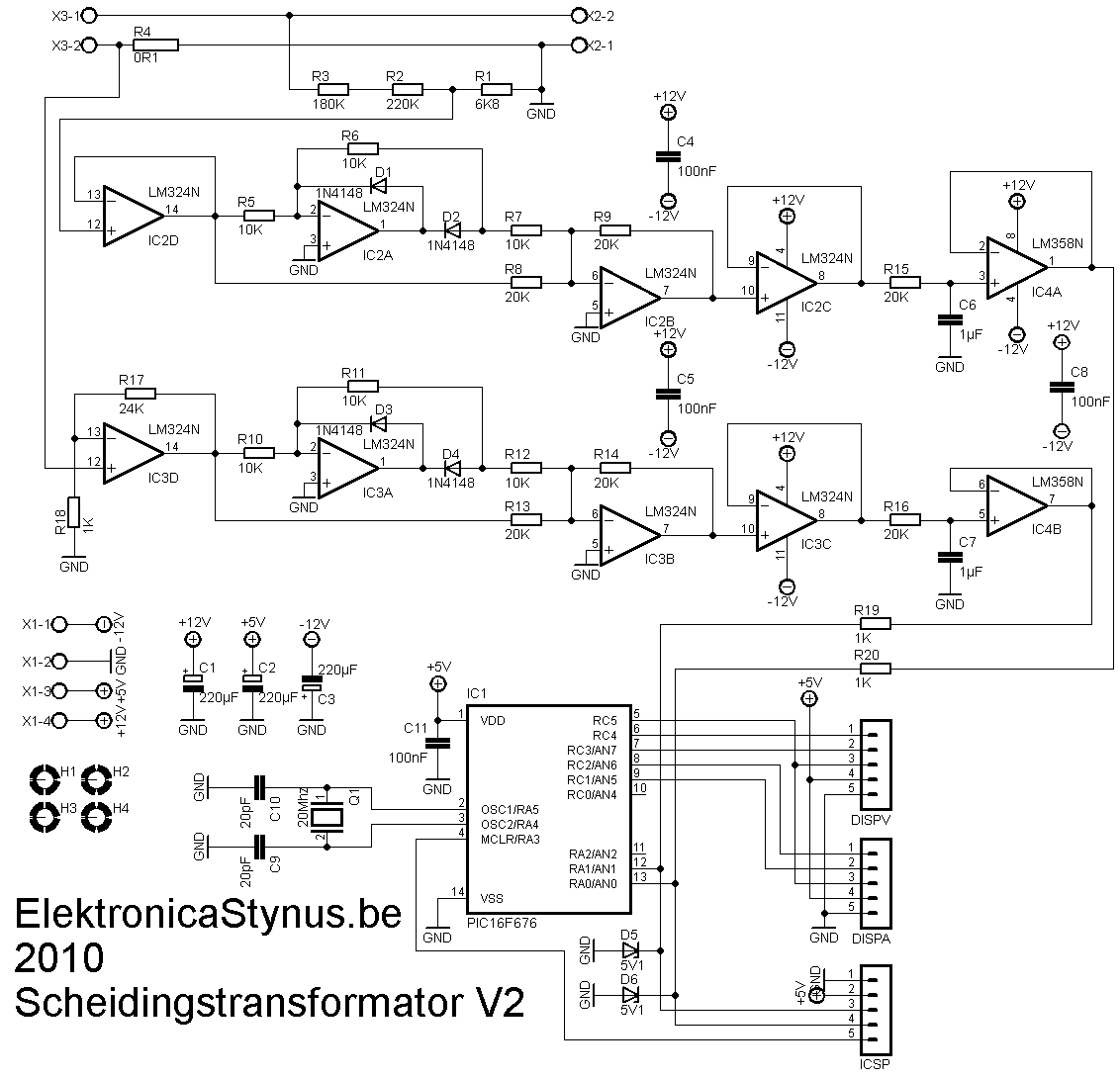
This time I wanted to put a voltage and current meter in it. I could just buy them, but where is the fun in that? So I made them myself. The voltage is lowered by a voltage divider, then rectified with a opamp precision rectifier. Then it is levelled by a RC filter which sends it in a AD converter. The current is measured with a 0,1 Ohm series resistor. Because off the current there is a voltage drop across the resistor that is proportional to the current. That voltage is amplified an rectified and let to the ad converter in the pic.
 |
 |

Display
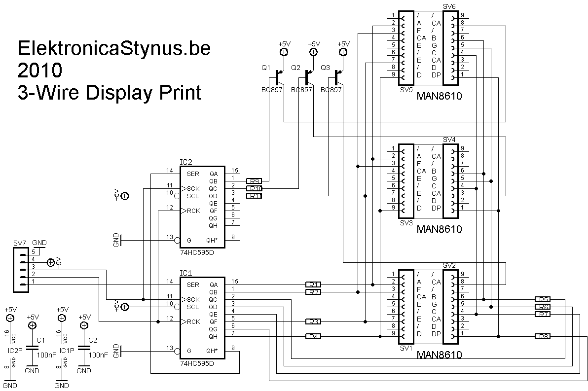
The pic has to drive 6 7-segment displays. To save IO pins to do this I have decided to make a circuit with 2x 74HC595 ic’s. Now it takes only 3 pins per display, so 6 pins in total. 1 of the 2 74HC595 ic’s selects witch 7 segment display is on, the other one drives the digits.
 |
 |


Light bulb indicators
To indicate witch lights are burning I made 3 holes in the front and let some optic fiber from there to the light bulbs.
Power supply
To power these 3 pcb’s I made a separate power supply pcb. It delivers +12V, -12V and +5V.
I used a transformer I had lying around, this transformer outputted 2*24V. This has the disadvantage that the 5V regulator gets very hot if I use a linear one. So I decided to use a switching one.
 |
 |

Main circuit
As you can read above, the current is limited by setting a light bulbs in series with the load. I have put 3 light bulbs in it, via 3 switches the bulbs can be selected. A forth switch can bypass the bulbs. To limit the output current then and switch the output on/off I used a 2A circuit breaker.
If you put 2 transformers “back to back” then you lose some voltage at the output. Therefore I’ve put a 60VA transformer that can put 15V on or of the output.
For the output I used 2 safety plugs and a wall socket.

Picture:

The front panel:

If I receive my PIC16F676 then I can start programming


