Some time ago I came across this design of an ESR meter. I then decided to build it, but for the display I wanted to use a pic + lcd.
My circuit:

(Clickable)
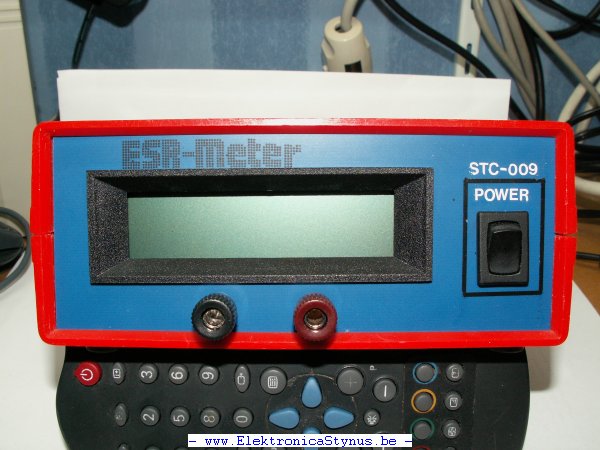
Pictures:


Jul 03 2008
Some time ago I came across this design of an ESR meter. I then decided to build it, but for the display I wanted to use a pic + lcd.
My circuit:
(Clickable)
Pictures:
Jul 22 2008
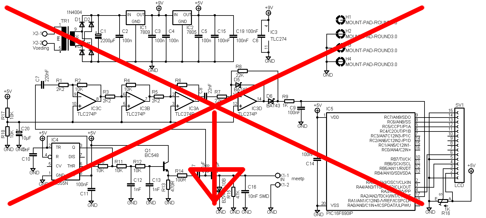
I made a mistake in my circuit. The non inverting inputs off the opamp should be connected to 2,5V instead of the ground. I could make a new pcb, but I decided to make it myself easy and made a special ic socket with a voltage divider build in.


The new circuit diagram:
Feb 24 2009
I got the code working. Apparently there is a bug in picbasic that gives problem with the AD on a 16F690. Therefore I made my own code to get the analogue value.
The code:
  Device 16F690
 Config INTRC_OSC_NOCLKOUT, WDT_OFF, PWRTE_OFF, MCLRE_OFF
 XTAL = 8
 OSCCON = %01110111

 Dim spanning As Word
 Dim esr As Float

 Declare LCD_DTPIN PORTC.4
 Declare LCD_ENPIN PORTC.3
 Declare LCD_RSPIN PORTB.6
 Declare LCD_LINES 2

 TRISA.2 = 1
 ADCON0 = %10000001
 ANSEL = %00000100
 ANSELH = %00000000

 ADIN_RES = 10
 ADIN_TAD = FRC
 ADIN_STIME = 500

 Symbol lcdTijd = 600
 Clear
 Cls
 Print At 1, 1, "ElektronicaStynu"
 Print At 2, 1, " ESR-Meter V1.2 "
 DelayMS lcdTijd
 Print At 1, 1, "lektronicaStynus"
 DelayMS lcdTijd
 Print At 1, 1, "ektronicaStynus."
 DelayMS lcdTijd
 Print At 1, 1, "ktronicaStynus.b"
 DelayMS lcdTijd
 Print At 1, 1, "tronicaStynus.be"
 DelayMS lcdTijd

 Cls
 Print At 1, 1, " ESR-Meter V1.2 "
 Print At 2, 1, " ESR = , "
 Print At 2, 16, $FE,$40,$00,$0E,$11,$11,$11,$0A,$1B,$00


While 1 = 1
 GoSub AD_in
 spanning = spanning - 480
 esr = spanning / 19
 If esr > 27 Then
 Print At 2, 9, "Open "
 Else
 Print At 2, 9, DEC2 esr , " "
 EndIf
 DelayMS 550


Wend
AD_in:
 ADCON0 = %10001001
 DelayMS 510
 ADCON0.1 = 1
 While ADCON0.1 = 1 : Wend
 spanning = 0
 spanning.HighByte = ADRESH
 spanning.LowByte = ADRESL


Return
End
Mar 26 2011
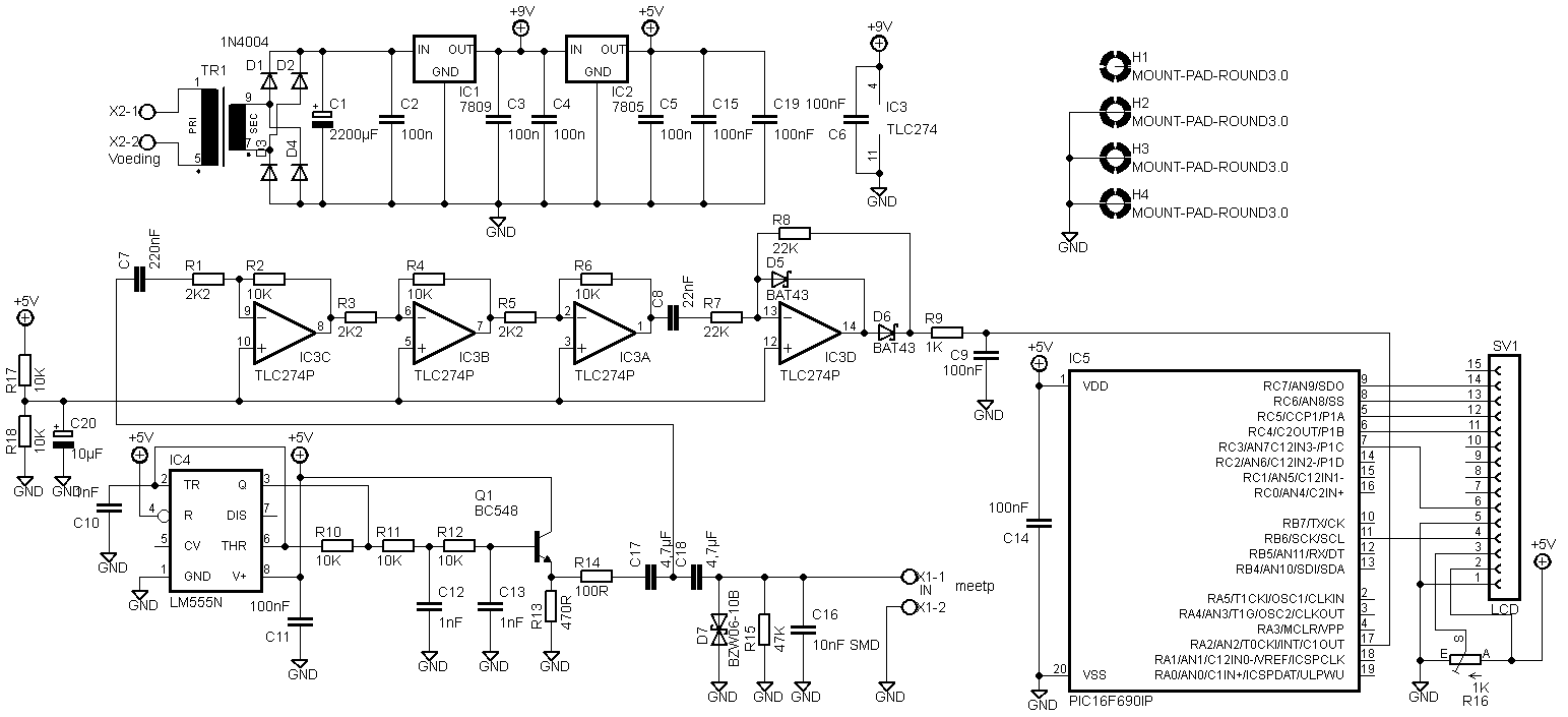
There was another adaptation on the pcb that was not in the circuit diagram above.

The LCD has to be connected differently. I don’t know why anymore, but here is the new circuit diagram:
I received Eagle files from Predrag Mihajlovic for this esr meter. They can be downloaded here: Link.
Hello,
I did 2 versions. First is one based on your schematics, except that I’ve changed those smd capacitors for standard through hole ones. Second one is somewhat modified. I’ve excluded transformer and put in standard dc jack. Also, pic and display header are located so far away from other stuff so that there is enough place for display to be on the pcb. Also, you’ll see that, on both versions I’ve also put pads for 27 and 22mm capacitors (4.7uF). Check it out and feel free to make any modifications you think are necessary. You can put it on your website if you like, maybe someone will find it useful 🙂
Peca.
